Understanding Three-Phase Transformers: Construction, Connections, and Applications
This comprehensive guide discusses three-phase transformers, crucial components in global electric generation and distribution systems. It explores different construction methods—using three single-phase transformers or a single transformer with a common core. Key connections like Wye-Wye, Wye-Delta, Delta-Wye, and Delta-Delta are outlined, with their advantages and potential issues, such as unbalanced loads and third harmonic voltages. The document also explains the implications of connecting transformers in various configurations, ensuring a thorough understanding for electrical engineering students.


Understanding Three-Phase Transformers: Construction, Connections, and Applications
E N D
Presentation Transcript
Three Phase Transformers • By Rahul Nehra (Lecturer,EE Deptt.)
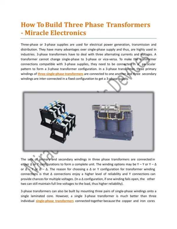
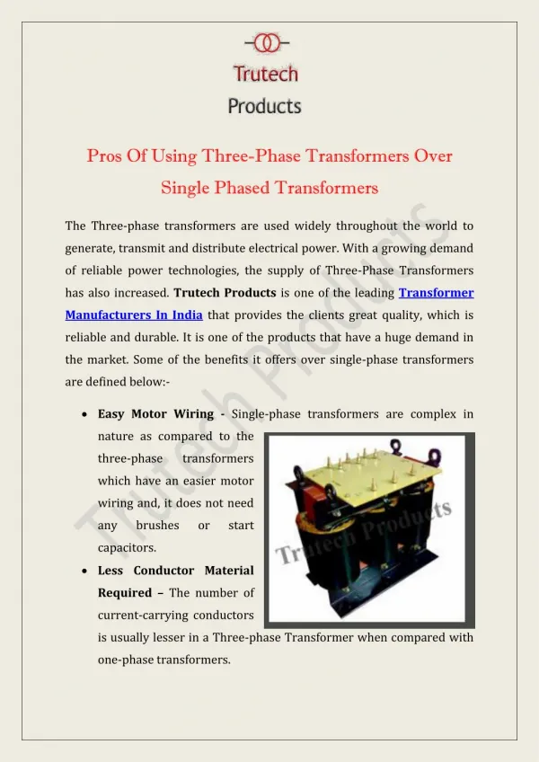
Almost all major generation & Distribution Systems in the world are three phase ac systems Three phase transformers play an important role in these systems Transformer for 3 phase cct.s is either: (a) constructed from 3 single phase transformers, or (b) another approach is to employ a common core for the three sets of windings of the three phases The construction of a single three phase transformer is the preferred today, it is lighter, smaller, cheaper and slightly more efficient There is an advantage that each unit in the bank could be replaced individually in the event of a fault, however this does not outweigh the other advantages of combined 3 ph. unit Three Phase Transformers
Three Phase Transformers • How the core of compact three phase is built • φa+φb+φc=0 and central leg can be removed
Three Phase Transformers • The two constructions
Three Phase Transformers • 3 phase transformer connections • The windings of primary and secondary (in any construction) can be connected in either a wye (Y) or delta (Δ) • This provides a total of 4 possible connections for 3 phase transformer (if Neutral is not grounded): (a) Wye-wye Y-Y (b) Wye-delta Y-Δ (c) Delta-wye Δ-Y (d) Delta-Delta Δ-Δ
Three Phase Transformers • To analyze a 3-phase transformer, each single transformer in the bank should be analyzed • Any single phase in bank behaves exactly like 1 phase transformer just studied • impedance, V.R., efficiency, & similar calculations for 3 ph. are done on per phase basis, using the same technique already used in single phase Transformer • The applications, advantages and disadvantages of each type of three phase connections will be discussed next
WYE-WYE connection In Y-Y connection, primary voltage on each phase is VφP=VLP/√3 Primary phase voltage is related to secondary phase voltage by turns ratio of transformer Phase voltage of secondary is related to Line voltage of secondary by VLS=√3 VφS Overall the voltage ratio of transformer is: Y-Y Three Phase Transformers
Three Phase Transformers • Two serious concerns on Y-Y connection 1- if loads on transformer cct. are unbalanced, voltages on phases of transformer severely unbalanced, also source is loaded in an unbalanced form 2- Third harmonic voltages can be large(there is no path for passage of third harmonic current) • Both concerns on unbalance load condition & large 3rd Harmonic voltages can be rectified as follows:
Three Phase Transformers • Solidly grounding the neutrals of windings specially primary winding, this connection provide a path for 3rd harmonic current flow, produced and do not let build up of large 3rd voltages . Also provides a return path for any current imbalances in load • Adding a third winding (tertiary) connected in Δ (a) 3rd harmonic components of voltage in Δ will add up, causing a circulating current flow within winding (b) tertiary winding should be large enough to handle circulating currents(normally 1/3 of power rating of two main windings) One of these corrective techniques should be employed with Y-Y, however normally very few transformer with this type of connection is employed (others can do the same job)
Three Phase Transformers • WYE-DELTA CONNECTION • VLP=√3 VφP, while : VLS= VφS • Voltage ratio of each phase : VφP/ VφS=a • VLP/ VLS= √3 VφP/ VφS= √3 a Y-Δ • Y-Δ doesn’t have shortcomings of Y-Y regarding generation of third harmonic voltage since the Δ provide a circulating path for 3rd Harmonic • Y-Δ is more stable w.r.t. unbalanced loads, since Δ partially redistributes any imbalance that occurs • This configuration causes secondary voltage to be shifted 30◦ relative to primary voltage • If secondary of this transformer should be paralleled with secondary of another transformer without phase shift, there would be a problem
Three Phase Transformers • WYE-DELTA CONNECTION
Three Phase TransformersY-Δ Connection • The phase angles of secondaries must be equal if they are to be paralleled, it means that direction of phase shifts also should be the same • In figure shown here, secondary lags primary if abc phase sequence applied, • However secondary leads primary when acb phase sequence applied
Three Phase TransformersΔ-Y Connection • DELTA-WYE CONNECTION • In Δ-Y primary line voltage is equal to primary phase voltage VLP=VφP, in secondary VLS=√3VφS • Line to line voltage ratio ; • VLP/ VLS = VφP/ [√3 VφS ]=a/√3 Δ-Y • This connection has the same advantages & phase shifts as Y- Δ • And Secondary voltage lags primary voltage by 30◦ with abc phase sequence
Three Phase TransformersΔ- Δ Connection • DELTA-DELTA CONNECTION • In Δ-Δ connection VLP= VφP and VLS= VφS • Voltage ratio : VLP/VLS= VφP / VφS =a Δ-Δ • This configuration has no phase shift and there is no concern about unbalanced loads or harmonics
THREE PHASE TRANSFORMERSPER UNIT • In 3 phase, similarly a base is selected • If Sbase is for a three phase system, the per phase basis is : S1φ,base= Sbase/3 • base phase current, and impedance are: • Iφ,base= S1φ,base/ Vφ,base= Sbase /(3Vφ,base) • Zbase=(Vφ,base)²/ S1φ,base • Zbase=3(Vφ,base)²/ Sbase • Relation between line base voltage, and phase base voltage depends on connection of windings, if connected in Δ ; VL,base=Vφ,base and • if connected in Wye: VL,base= √3Vφ,base • Base line current in 3 phase transformer: • IL,base= Sbase/ (√3 VL,base)
Apparent Power Rating of a Transformer • Apparent power rating & Voltage rating set current flow of windings • Current flow important as it controls I²R losses in turn control heating of coils Heating is critical, since overheating the coils reduce insulation life • Actual VA rating of a transformer may be more than a single value: In real Transformer: (a) may be a VA rating for transformer by itself, (b) another (higher) rating for transformer with forced cooling • If a transformer’s voltage reduced for any reason (i.e. operating with lower frequency than normal)then transformer VA rating must reduced by an equal amount, otherwise current exceed permissible level & cause overheating
Inrush Current • This is caused by applied voltage level at energization of transformer, or due to residual flux in the transformer core • Suppose that voltage is : v(t)=VM sin(ωt+θ) V • The maximum flux reached during first half-cycle of applied voltage depends on θ • If θ=90◦ or : v(t)=VM cos(ωt) & no residual flux in core max. flux would be : φmax=Vmax/(ωNP) • However if θ=0 the max. flux would be φmax=2Vmax/(ωNP) and is twice the steady-state flux
Inrush Current • With this high maximum flux if the magnetization curve examined it shows passage of enormous magnetizing current, (looks like short circuit in part of cycle) • In these cases that θ is not 90◦ this excess current exist, therefore power system & transformer must be able to withstand these currents