Download
1 / 98
1.04k likes | 1.17k Vues
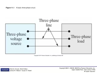
Learn about single-phase, two-phase, and three-phase circuits, balanced voltages, and the importance of three-phase systems. Explore phase sequences, power generation, and circuit behavior.

E N D
THREE PHASE CIRCUIT Made by: Vivek pal (13ELEE557) Sher singh (13ELEE564) Gagandeep (13ELEE552) Harsh patel (13ELEE549) Guided by: Sudhir pandey
Objectives • Explain the differences between single-phase, two-phase and three-phase. • Compute and define the Balanced Three-Phase voltages. • Determine the phase and line voltages/currents for Three-Phase systems.
SINGLE PHASE SYSTEM • A generator connected through a pair of wire to a load – Single Phase Two Wire. • Vp is the magnitude of the source voltage, and is the phase.
SINGLE PHASE SYSTEM • Most common in practice: two identical sources connected to two loads by two outer wires and the neutral: Single Phase Three Wire. • Terminal voltages have same magnitude and the same phase.
POLYPHASE SYSTEM • Circuit or system in which AC sources operate at the same frequency but different phases are known as polyphase.
POLYPHASE SYSTEM • Two Phase System: • A generator consists of two coils placed perpendicular to each other • The voltage generated by one lags the other by 90.
POLYPHASE SYSTEM • Three Phase System: • A generator consists of three coils placed 120 apart. • The voltage generated are equal in magnitude but, out of phase by 120. • Three phase is the most economical polyphase system.
IMPORTANCE OF THREE PHASE SYSTEM • All electric power is generated and distributed in three phase. • One phase, two phase, or more than three phase input can be taken from three phase system rather than generated independently. • Melting purposes need 48 phases supply.
IMPORTANCE OF THREE PHASE SYSTEM • Uniform power transmission and less vibration of three phase machines. • The instantaneous power in a 3 system can be constant (not pulsating). • High power motors prefer a steady torque especially one created by a rotating magnetic field.
IMPORTANCE OF THREE PHASE SYSTEM • Three phase system is more economical than the single phase. • The amount of wire required for a three phase system is less than required for an equivalent single phase system. • Conductor: Copper, Aluminum, etc
FARADAYS LAW • Three things must be present in order to produce electrical current: • Magnetic field • Conductor • Relative motion • Conductor cuts lines of magnetic flux, a voltage is induced in the conductor • Direction and Speed are important
S N GENERATING A SINGLE PHASE Motion is parallel to the flux. No voltage is induced.
S N x GENERATING A SINGLE PHASE Motion is 45° to flux. Induced voltage is 0.707 of maximum.
S N x GENERATING A SINGLE PHASE Motion is perpendicular to flux. Induced voltage is maximum.
S N x GENERATING A SINGLE PHASE Motion is 45° to flux. Induced voltage is 0.707 of maximum.
S N GENERATING A SINGLE PHASE Motion is parallel to flux. No voltage is induced.
S N x GENERATING A SINGLE PHASE Motion is 45° to flux. Notice current in the conductor has reversed. Inducedvoltage is 0.707 of maximum.
S N x GENERATING A SINGLE PHASE Motion is perpendicular to flux. Induced voltage is maximum.
S N x GENERATING A SINGLE PHASE Motion is 45° to flux. Induced voltage is 0.707 of maximum.
S N GENERATING A SINGLE PHASE Motion is parallel to flux. No voltage is induced. Ready to produce another cycle.
GENERATOR WORK • The generator consists of a rotating magnet (rotor) surrounded by a stationary winding (stator). • Three separate windings or coils with terminals a-a’, b-b’, and c-c’ are physically placed 120 apart around the stator.
As the rotor rotates, its magnetic field cuts the flux from the three coils and induces voltages in the coils. • The induced voltage have equal magnitude but out of phase by 120.
S x x N GENERATION OF THREE-PHASE AC
Phase 1 Phase 2 Phase 3 120° 120° 120° 120° 120° 120° 240° 240° THREE-PHASE WAVEFORM Phase 2 lags phase 1 by 120°. Phase 2 leads phase 3 by 120°. Phase 3 lags phase 1 by 240°. Phase 1 leads phase 3 by 240°.
Phase 1 Phase 2 Phase 3 S x x N GENERATION OF 3 VOLTAGES Phase 1 is ready to go positive. Phase 2 is going more negative. Phase 3 is going less positive.
BALANCED 3 VOLTAGES • Balanced three phase voltages: • same magnitude (VM ) • 120 phase shift
BALANCED 3 CURRENTS • Balanced three phase currents: • same magnitude (IM ) • 120 phase shift
PHASE SEQUENCE NEGATIVE SEQUENCE POSITIVE SEQUENCE
EXAMPLE # 1 • Determine the phase sequence of the set voltages:
BALANCED VOLTAGE AND LOAD • Balanced Phase Voltage: all phase voltages are equal in magnitude and are out of phase with each other by 120. • Balanced Load: the phase impedances are equal in magnitude and in phase.
THREE PHASE CIRCUIT • POWER • The instantaneous power is constant
THREE PHASE CIRCUIT • Three Phase Power,
PHASE VOLTAGES and LINE VOLTAGES • Phase voltage is measured between the neutral and any line: line to neutral voltage • Line voltage is measured between any two of the three lines: line to line voltage.
PHASE CURRENTS and LINE CURRENTS • Line current (IL) is the current in each line of the source or load. • Phase current (I) is the current in each phase of the source or load.
SOURCE-LOAD CONNECTION • Common connection of source:WYE • Delta connected sources: the circulating current may result in the delta mesh if the three phase voltages are slightly unbalanced. • Common connection of load:DELTA • Wye connected load: neutral line may not be accessible, load can not be added or removed easily.