Post Anneal Solid State Regrowth
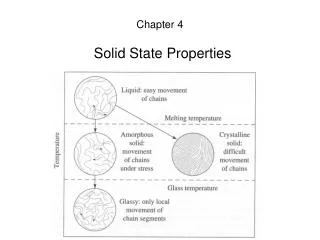
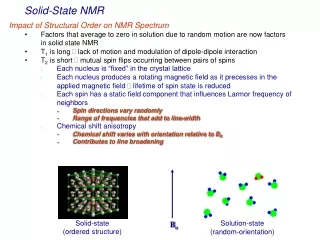
Post Anneal Solid State Regrowth. Implant Annealing/Activation. Ion. Individual Collision Cascades for < 10 12 cm -2. X-tal Surface. Amorphous Layer for > 10 15 cm -2. Damaged X-tal or Amorphous. Annealing - SSER > 450 C - Point Defects - Extended Defects Activation


Post Anneal Solid State Regrowth
E N D
Presentation Transcript
Implant Annealing/Activation Ion Individual Collision Cascades for < 1012 cm-2 X-tal Surface Amorphous Layer for > 1015 cm-2 Damaged X-tal or Amorphous Annealing - SSER > 450 C - Point Defects - Extended Defects Activation - Substitutional Sites Target Atom X-tal Bulk
Notes: • Damage heaviest near end of range because: • a) Cross-section for collision increases • b) More ions due damage as there are also knock on Silicon atoms with sufficient energy to do damage. • c) Even if all vacancies created perfectly recombine with all interstitials created, there will be a surplus of interstitials as the implanted dopant “takes over a silicon lattice site. Known as the “n+1” model.
Annealing/Activation End-of-Range (EOR) Dislocation Loops After Solid Phase Epitaxial Regrowth Concentration PDG 8-25 2000 Depth
Notes • Above threshold (~ 1E15 per/cm2 ) Silicon is amorphous • Heaviest crystal damage is just below amorphous layer • Damage consists mostly of interstitial loops, and 311 defects. • Damage is very difficult to anneal out, as the loops in most cases can not “glide” to surface. • As long as damage layer is far away from device layer (top) no ill effects ( • Positive effects of EOR defects: gettering and supressing latch up.
Activated Fraction Implant B-> Si 70 keV 1015 cm-2 Anneal 800 or 900 C 35 min 800 C 900 C Depth (mm) SIMS SIMS Hall Hall After Sze, Fig. 24, p. 357 Concentration (cm-3)
Tem, x 40 k , 2E15 Boron, 50 KeV Annealed at 700 C Annealed at 800 C
Notes • SIMS (Secondary Ion Mass spectroscopy) is a technique that destructively sputter-etches a flat bottom crater into a semiconductor, using Ar or Cs ions. The ejected matter is analyzed and yields impurity concentration vs. depth. • SIMS counts the total number of dopant atoms (e.g 1E19/cm3 Boron). • Hall counts the total number of mobile carriers generated by the dopant. • For the two to be same: (i) all dopants must be activated and (b) all mobile charge must be mobile. In particular, no charge can be trapped anywhere in the specimen.
Trapping Electrical measurements measure mobile carriers only. A low “activated fraction” could reflect a) low fraction of dopants on lattice sites and no traps or b) a high fraction of dopants on lattice sites but many traps (e.g defect clusters)
Implant/Anneal Examples 1021 Implant B-> Si 35 keV Anneals RTA 1100 C/10 s RTA 1100 C/30 s F 1000 C/30 m Concentration (cm-3) F RTA I Sze, Fig. 29, p. 362 1015 0 1 Depth (mm) Furnace Anneal “peak” indicative of B cluster formation.
Implant/Anneal Examples Transient Enhanced Diffusion (TED) Anomalous Diffusion After Ion Implantation Concentration (cm-3) PDG 8-31 2000 Depth (mm) D (Boron) at 1000 C is a 100 times larger than at 800 C. Yet a 12 times longer anneal at 800 C generates a deeper profile !
Notes • The original key idea to rapid thermal annealing is that dopant diffusion (EA ~ 4 eV) varies less with temperature than lattice repair (EA ~ 5 eV) . The difference at high temperature does not look like much but this is a log plot !
Unfortunately, it got much more complicated Impurities diffuse by exchanging position with vacancies (Sb), or with interstitials (B) or with both (P). The key in understanding rapid thermal processing was to understand the (very time dependent) excess concentration of point defects above their equilibrium value. Scientifically, the supersaturation of point defects.
Key Ideas in Transient Enhanced Diffusion (TED). • Annealing starts with the “falling apart” of vacancy clusters. The clusters are analogous to small water droplets. The smaller the droplet, the higher the vapor pressure. Thus, once the first vacancy “evaporates” from a small vacancy cluster, the remaining - now smaller cluster - is more unstable than before, and the next vacancy evaporates faster. This process sets in above 400 C (depends on implant temperature). • The great majority of vacancies recombine with interstitials • A few vacancies escape to the surface. Since the surface is further away than the next interstitial, the process is slower and accessible only to vacancies close to the surface. • Interstitials are left over, as their lattice sites are occupied by the implanted dopants. The interstitials condense into {311} defects..
PDG The 311 defects lie on {311} planes. They are long and thin and extend into the <110> directions. Low density of {311} => they evaporate into interstitials High density of {311} => large one grow at expense of small ones and turn into ultra stable loops
Key ideas on role of {311} defects: • They store interstitials • During rapid thermal annealing, they fall apart, evaporating interstitials. • The evaporated interstititials exert a “vapor pressure”. When the pressure reaches a critical value, other {311} defects are prevented from falling apart. • The result is that the concentration of interstitials is pegged at this critical value. The supersaturation of interstitials is 1000 (higher T) to 10000 (lower T) • Impurities moving by exchange with interstitials (such as B) will diffuse MUCH faster than anticipated.
Low implant dose Supersaturation of Si Self Interstitials Time High implant dose A larger dose does not make TED “faster”, it just makes it last longer !
PDG Transmission electron microscopy showed that the {311} defects fall apart in about 100 sec at 815 C and about 100 000 sec at 678. Note: At high temperatures interstitials are very mobile. There mean free path is 100’s of microns in clean silicon
Can you see an interstitial in the TEM ? Not yet !!! So how do we know they are there ? • Growth and shrinkage of defects that store interstititials such as stacking faults, helical dislocations, {311} defects. • Rutherford backscattering => we now explore the channeling effect !