Download
1 / 29
380 likes | 891 Vues
Chapter 7. DESIGN OF TRUSS ROOF. University of Engineering & Technology, Taxila. TABLE OF FORCES There are three important points to be considered while calculating the member forces: Panel load multiplied with unit load forces gives the member forces by the principle of superposition.

E N D
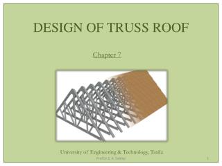
Chapter 7 DESIGN OF TRUSS ROOF University of Engineering & Technology, Taxila Prof Dr Z. A. Siddiqi
TABLE OF FORCES • There are three important points to be considered while calculating the member forces: • Panel load multiplied with unit load forces gives the member forces by the principle of superposition. • According to this principle, which is applicable for elastic structures, if a unit load is applied on a truss and the force in any member is calculated as F; thenif we apply another unit load simultaneously at the same point, the force in the member will be 2F. Prof Dr Z. A. Siddiqi
Similarly, this member force will be 3Fforthree unit loads or P x Fif Ptimes unit loads are applied. • Effects of various types of loads are to be added while calculating member forces. • Vertical and inclined loads on the truss cannot be added directly because of different lines of action of each. • However, separate member forces due to vertical and inclined loads have the same direction (along the member longitudinal axis) and hence can be algebraically added together. Prof Dr Z. A. Siddiqi
Probability of occurrence of various loads in a load combination and corresponding load factors (factor of safety) are also applied during these calculations. • In case only dead, live and wind loads are acting on a truss, following combinations may be investigated: 1. 1.2D + 1.6Lr + 0.65W (Wind effect is small and may be ignored especially suction is present throughout) Prof Dr Z. A. Siddiqi
2. 1.2D + 0.5Lr + 1.3W Wind towards the Right Wind towards the left 3. 0.9D + 1.3W Wind towards the Right Wind towards the Left • For the roof design, the first (gravity) or second (wind) load combination is critical. It is to be noted that the downward wind load is to be considered in the second combination. Prof Dr Z. A. Siddiqi
The third combination is critical for reversal of forces and hence is evaluated for upward wind pressures. • In case the wind load has two values, one downward and one upward, the downward value should be used for the second combination and the upward value should be used for the third combination. • It would be unreasonable to include full wind and full snow (or live load) stresses together in a single combination. Prof Dr Z. A. Siddiqi
Similarly, when the wind is blowing at its full strength, the live load intensity may be reduced. • The second combination reflects the condition when most severe windstorm is blowing and hence the live load intensity may be reduced to 0.5/ 1.6 or 0.31 times its maximum intensity, showing less probability of occurrence of full live load together with wind. • The third combination represents an unoccupied building subjected to the heaviest wind. Prof Dr Z. A. Siddiqi
The negative sign with the wind forces only indicates that the combination is critical when the wind is producing member forces opposite in sense to that produced by the dead loads. • The design forces may be calculated by entering the values into a Table of Forces as in Table 7.2. • The first four columns of this table are directly taken from the unit load analysis of the truss while columns 5 to 9 are calculated using the first four columns and the algebraic values of the panel loads, already determined. Prof Dr Z. A. Siddiqi
Sample Table of Forces Prof Dr Z. A. Siddiqi
After getting the values in these columns, the maximum factored tension and compression may be found out and entered in the next two columns. • Usually tension is represented by positive sign and compression by a negative sign in columns 2 to 4 and hence maximum tension is defined as the maximum positive value and maximum compression as the minimum value (maximum negative answer) in columns 5 to 9. Prof Dr Z. A. Siddiqi
The remarks column is used to describe the type of the member for design such as pure tension member, pure compression member, member under reversal of stresses and zero force member. • A computer spreadsheet may conveniently be used to construct such a table. • The truss members may now be selected by using the procedure given in earlier chapters and connections may be designed by the methods outlined in the coming chapters. Prof Dr Z. A. Siddiqi
Sample Table of Forces Prof Dr Z. A. Siddiqi
Pww Pww= +ve (1.2PD+0.5PL) X COL. 2 + 1.3 PWW X COL. 3
Pwl Pww Pww= +ve (1.2PD+0.5PL) X COL. 2 + 1.3 PWW X COL. 3 Pwl= -ve
Load Combination in Column No 6 Pwl Pww Pww= +ve (1.2PD+0.5PL) X COL. 2 + 1.3 PWW X COL. 3 + 1.3 PWL X COL. 4 Pwl= -ve
Pwl Pww Pww= +ve (1.2PD+0.5PL) X COL. 2 + 1.3 PWW X COL. 3 + 1.3 PWL X COL. 4 Pwl= -ve
Sample Table of Forces Prof Dr Z. A. Siddiqi
Load Combination in Column No 7 Pwl Pww Pww= +ve (1.2PD+0.5PL) X COL. 2 + 1.3 PWW X COL. 4 + 1.3 PWL X COL. 3 Pwl= -ve
Sample Table of Forces Prof Dr Z. A. Siddiqi
Load Combination in Column No 8 Pwl Pww Pww= -ve (0.9PD) X COL. 2 + 1.3 PWW X COL. 3 + 1.3 PWL X COL. 4 Pwl= -ve
Sample Table of Forces Prof Dr Z. A. Siddiqi
Load Combination in Column No 9 Pwl Pww Pww= -ve (0.9PD) X COL. 2 + 1.3 PWW X COL. 4 + 1.3 PWL X COL. 3 Pwl= -ve
Sample Table of Forces Prof Dr Z. A. Siddiqi
Assignment: Draw the Table of Forces for Your Data & find the Truss Member Forces. Time Allowed: 1 week