Download
1 / 60
2.93k likes | 8.25k Vues
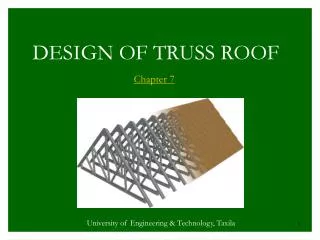
Chapter 7. DESIGN OF TRUSS ROOF. University of Engineering & Technology, Taxila. Properties of Trusses Truss is a frame structure in which all the members have axial forces due to the following facts: Members are arranged in triangles for stability.

E N D
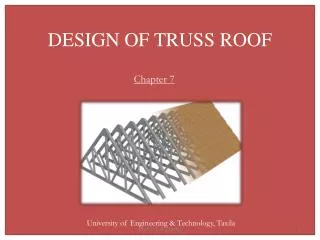
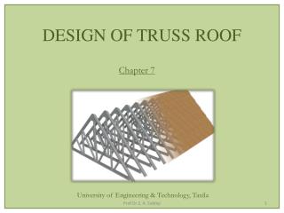
Chapter 7 DESIGN OF TRUSS ROOF University of Engineering & Technology, Taxila
Properties of Trusses Truss is a frame structure in which all the members have axial forces due to the following facts: • Members are arranged in triangles for stability. • All the joints of a truss are semi-rigid or fully rigid. However, theoretically these joints may be considered pin joints and the analysis as a pin jointed frame is valid provided that the requirements given in No. 3 & 4 are valid.
Centroidal axes of all the members at a joint must intersect at a single point. • The loads are only applied at the panel points. Comparison Between Rigid Frames and Trusses • Joints are considered as having frictionless pins in trusses with no moment at the member ends. In case of rigid frames, the members are rigidly connected having appreciable moments at the member ends.
The forces in case of trusses are only axial and hence the members are equally stressed through-out their cross-section. In rigid frames, due to bending moment, the fibers of the cross-section away from the neutral axis have maximum stresses and the fibers close to the neutral axis have less stress. • Because of the above facts, the design of a member in a truss is economical as compared with the members of a rigid frame.
Types of Trusses • Trusses can be divided into two categories, Type-I & Type-II. • Type-I trusses are preferred in those areas where snow fall is common and Type-II trusses are used in hot climates. • The roofs of Type-I trusses are inclined at greater angles (10° to 60°) to drain part of the snow falling on the roof surface.
Types of Trusses • The roofs of Type-II trusses are either nearly flat or are inclined at angles less than 10°. • If the forces in the diagonal members are all compressive and that in the vertical members are all tensile, the truss is called Howe Truss.
Types of Trusses • In a reverse way if the forces in all the diagonal members are tensile while the forces in all the vertical members are compressive, the truss is called Pratt Truss. • The difference between these two trusses is only the orientation of the diagonals in relation to the applied loads. • For all the given trusses, the loads are in general applied at the top chord.
Type-I Trusses Queen Post ( L ≤ 12 m)
Type-I Trusses Upper Chord Slope h = rise ø L= span Lower Chord King Post ( L ≤ 12 m)
Type-I Trusses Fink Truss ( L = 8 - 10 m)
Type-I Trusses Fan Truss ( L = 10 - 15 m)
Type-I Trusses Compound Fink or French Truss ( L = 10 - 15 m)
Type-I Trusses Subdivided Fink Truss ( L = 10 - 15 m)
Type-I Trusses Radius R = (4h + L)/8h Bowstring Truss
Type-I Trusses Parker or Bowstring Truss
Type-I Trusses Radius R = (4h + L)/8h Radius R = (4r + L)/8r h = rise r CrescentBowstring Truss
Type-I Trusses Compound Fan Truss ( L = 15 - 25 m)
Type-I Trusses Pratt Truss ( L = 10 - 30 m)
Type-I Trusses Howe Truss ( L = 10 - 30 m)
Type-I Trusses North Light Truss ( L = 5 - 8 m)
Type-I Trusses Saw Tooth Truss ( L = 5 - 8 m)
Type-I Trusses Glass Ketchum’s Modified Saw Tooth Truss ( L = 8 - 10 m)
Type-I Trusses Monitor Truss ( L = 10 - 15 m)
Type-II Trusses Modified Howe Truss ( L ≤ 40 m)
Type-II Trusses L/8 L/12 Modified Pratt Truss ( L ≤ 40 m)
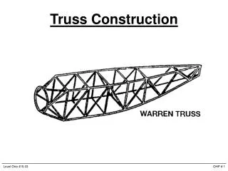
Type-II Trusses Warren Truss ( L ≤ 45 m)
Type-II Trusses K - Truss ( L ≤ 60 m)
Type-II Trusses Warren ( L ≤ 40 m)
Type-II Trusses Cantilever Truss ( L ≤ 60 m)
Terms Related With Trusses Pitch of a Roof Truss Pitch of a roof truss is defined as the maximum rise of top chord of the truss (h) divided by the total span of the truss (L). For symmetrical trusses the pitch is equal to double the inclination of the top chord. Pitch = h / L
Pitch of a Roof Truss h = rise L= span Pitch = h / L
Inclination of a Roof Truss The slope (tan θ) or angle (θ) of top chord of a truss with respect to the horizontal is called inclination of the truss. For un-symmetrical trusses, inclination may be completely independent of the pitch of the trusses. For Type-I trusses, θ ≤ 60° (most suitable range 20° -30°) For Type-II trusses, θ ≤ 10°
Inclination of a Roof Truss Slope ø
Height / Rise of Truss The maximum height of the truss (h) with respect to the ends of the bottom chord is called height or rise of the truss. The highest point is called crown of the truss. For Type-I trusses, h = L/3 to L/5 (most suitable value L/4) For Type-II trusses, h = L/8 to L/12 (most suitable value L/10)
Height/Rise of Truss h = rise
Panel Length In case of roof trusses, the distance between two consecutive top chord joints is known as the panel length. If panel length is more, the perpendicular beams supporting the roof (called purlins) have to be placed within the top chord members producing bending moment in the truss members.
Panel Length The reason of doing this is that the usual roof coverings can not have greater span lengths. Panel lengths can be the projected horizontal or the actual inclined lengths. Panel lengths for type-I trusses = 1 to 3m (most appropriate value 1.8m) Panel lengths for type-II trusses = 3 to 4m
Purlins These are small beams which run perpendicular to the trusses and rest at the panel points of the trusses. The purlins provide the lateral bracing to the top chord and carry the load of the roof transferring it to the panel points of the trusses.
Purlins The span of these beams is equal to the centre-to-centre spacing of the trusses. Usually the purlins are continuous over the trusses but are designed as simply supported for convenience of design and construction.
Purlins The purlins may consist of angle sections, channel sections or I-sections. Small depth trusses may be used as purlins if the spacing of the trusses is more. Zee section purlins are preferable for inclined roofs if they are easily available.
Purlins The angle and the channel purlins are connected to the top chord (sometimes called rafter) by cleat angles as shown. I-section purlins are usually bolted to the top chord.
Purlins Because of the inclination of the roof, a component of load acts along both the centroidal axes of the member producing both in plane and lateral bending known as double or biaxial bending. Sag rods may be used with channels or other sections to reduce lateral bending.
Purlins The nature of the loading on the purlin requires a beam section that is strong in bending about both the axes. For this reason, W-sections are preferred when the loads are heavy and the spans are bigger.
Clip or Cleat Angles These angles are previously bolted, riveted, or welded to the top chord above which the purlins may rest while it is being fastened to the truss.
Sag Rods When channels are used for purlins, it is good design practice to use sag rods to take the tangential component of the roof loads. These are placed either at mid span or at the third points, depending on the weight of the roof, the span of the purlins, and the pitch of the roof truss.
Sag Rods Max. span of purlin for one sag rod = 6 m (light roof) = 4.5 m (heavy roof) For roofs steeper than a pitch of 1/4 , two sag rods should be used for a purlin span of 4.5 m.
Roof Covering / Sheathing Light roofing: Corrugated Galvanized Iron (G.I) sheets Corrugated Asbestos Cement Concrete (A.C.C.) sheets Heavy roofing: Clay or cement tiles Gypsum tiles Slate tiles Tar plus gravel