Software Design: Concepts and Principles for Effective Development
Learn about software design process, from requirements analysis to modular design principles for efficient software development. Explore conceptual and technical design aspects to satisfy customer needs and enhance system builders' experience.


Software Design: Concepts and Principles for Effective Development
E N D
Presentation Transcript
Software Design
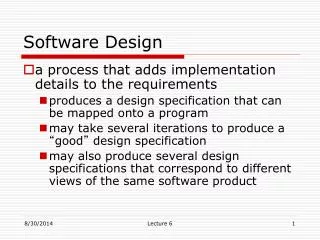
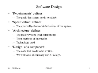
Software Design • More creative than analysis • Problem solving activity WHAT IS DESIGN ‘HOW’ Software design document (SDD)
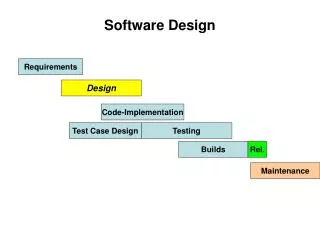
Initial requirements Gather data on user requirements Analyze requirements data Validate the design against the requirements Obtain answers to requirement questions Conceive of a high level design Refine & document the design Completed design Software Design Fig. 1 : Design framework
Software Design design Satisfy Customer Developers (Implementers)
Designers How What Technical design Conceptual design A two part design process System Builders Customer Software Design Conceptual Design and Technical Design Fig. 2 : A two part design process
Software Design Conceptual design answers : • Where will the date come from ? • What will happen to data in the system? • How will the system look to users? • What choices will be offered to users? • What is the timings of events? • How will the reports & screens look like?
Software Design Technical design describes : • Hardware configuration • Software needs • Communication interfaces • I/O of the system • Software architecture • Network architecture • Any other thing that translates the requirements in to a solution to the customer’s problem.
Software Design The design needs to be • Correct & complete • Understandable • At the right level • Maintainable
Informal design outline Informal design More formal design Finished design Software Design Fig. 3 : The transformation of an informal design to a detailed design.
Software Design MODULARITY There are many definitions of the term module. Range is from : • Fortran subroutine • Ada package • Procedures & functions of PASCAL & C • C++ / Java classes • Java packages • Work assignment for an individual programmer
Software Design All these definitions are correct. A modules system consist of well defined manageable units with well defined interfaces among the units.
Software Design Properties : • Well defined subsystem • Well defined purpose • Can be separately compiled and stored in a library. • Module can use other modules • Module should be easier to use than to build • Simpler from outside than from the inside.
Software Design Modularity is the single attribute of software that allows a program to be intellectually manageable. It enhances design clarity, which in turn eases implementation, debugging, testing, documenting, and maintenance of software product.
Software Design Fig. 4 : Modularity and software cost
Software Design Module Coupling Coupling is the measure of the degree of interdependence between modules. (Uncoupled : no dependencies) (a)
Software Design Highly coupled: many dependencies (C) Loosely coupled: some dependencies (B) Fig. 5 : Module coupling
Software Design This can be achieved as: • Controlling the number of parameters passed amongst modules. • Avoid passing undesired data to calling module. • Maintain parent / child relationship between calling & called modules. • Pass data, not the control information.
Edit student record Edit student record Student name, student ID, address, course Student record EOF Student record EOF Student ID Retrieve student record Retrieve student record Software Design Consider the example of editing a student record in a ‘student information system’. Poor design: Tight Coupling Good design: Loose Coupling Fig. 6 : Example of coupling
Software Design Fig. 7 : The types of module coupling Given two procedures A & B, we can identify number of ways in which they can be coupled.
Software Design Data coupling The dependency between module A and B is said to be data coupled if their dependency is based on the fact they are communicate by only passing of data. Other than communicating through data, the two modules are independent. Stamp coupling Stamp coupling occurs between module A and B when complete data structure is passed from one module to another.
Software Design Control coupling Module A and B are said to be control coupled if they communicate by passing of control information. This is usually accomplished by means of flags that are set by one module and reacted upon by the dependent module. Common coupling With common coupling, module A and module B have shared data. Global data areas are commonly found in programming languages. Making a change to the common data means tracing back to all the modules which access that data to evaluate the effect of changes.
Software Design Fig. 8 : Example of common coupling
Software Design Content coupling Content coupling occurs when module A changes data of module B or when control is passed from one module to the middle of another. In Fig. 9, module B branches into D, even though D is supposed to be under the control of C.
Software Design Fig. 9 : Example of content coupling
Software Design Module Cohesion Cohesion is a measure of the degree to which the elements of a module are functionally related. Module strength Fig. 10 : Cohesion=Strength of relations within modules
Software Design Types of cohesion • Functional cohesion • Sequential cohesion • Procedural cohesion • Temporal cohesion • Logical cohesion • Coincident cohesion
Software Design Fig. 11 : Types of module cohesion
Software Design Relationship between Cohesion & Coupling If the software is not properly modularized, a host of seemingly trivial enhancement or changes will result into death of the project. Therefore, a software engineer must design the modules with goal of high cohesion and low coupling. Fig. 12 : View of cohesion and coupling
Software Design STRATEGY OF DESIGN A good system design strategy is to or organize the program modules in such a way that are easy to develop and latter to, change. Structured design techniques help developers to deal with the size and complexity of programs. Analysts create instructions for the developers about how code should be written and how pieces of code should fit together to form a program. It is important for two reasons: • First, even pre-existing code, if any, needs to be understood, organized and pieced together. • Second, it is still common for the project team to have to write some code and produce original programs that support the application logic of the system.
Software Design Bottom-Up Design These modules are collected together in the form of a “library”. Fig. 13 : Bottom-up tree structure
Software Design Top-Down Design A top down design approach starts by identifying the major modules of the system, decomposing them into their lower level modules and iterating until the desired level of detail is achieved. This is steps wise refinement; starting from an abstract design, in each step the design is refined to a more concrete level, until we reach a level where no more refinement is needed and the design can be implemented directly.
Software Design Hybrid Design For top-down approach to be effective, some bottom-up approach is essential for the following reasons: • To permit common sub modules. • Near the bottom of the hierarchy, where the intuition is simpler, and the need for bottom-up testing is greater, because there are more number of modules at low levels than high levels. • In the use of pre-written library modules, in particular, reuse of modules.
Software Design FUNCTION ORIENTED DESIGN Function Oriented design is an approach to software design where the design is decomposed into a set of interacting units where each unit has a clearly defined function. Thus, system is designed from a functional viewpoint.
Software Design Consider the example of scheme interpreter. Top level function may look like:
Software Design We continue the refinement of each module until we reach the statement level of our programming language. At that point, we can describe the structure of out program as a tree of refinement as in design top-down structure as shown in fig. 14. Fig. 14 : Top-down structure
Software Design If a program is created top-down, the modules become very specialized. As one can easily see in top down design structure, each module is used by at most one other module, its parent. For a module, however, we must require that several other modules as in design reusable structure as shown in fig. 15. Fig. 15 : Design reusable structure
Software Design Design Notations Design notations are largely meant to be used during the process of design and are used to represent design or design decisions. For a function oriented design, the design can be represented graphically or mathematically by the following: • Data flow diagrams • Data Dictionaries • Structure Charts • Pseudocode
Software Design Structure Chart It partition a system into block boxes. A black box means that functionality is known to the user without the knowledge of internal design. Fig. 16 : Hierarchical format of a structure chart
Software Design Fig. 17 : Structure chart notations
Software Design A structure chart for “update file” is given in fig. 18. Fig. 18 : Update file
Software Design A transaction centered structure describes a system that processes a number of different types of transactions. It is illustrated in Fig.19. Fig. 19 : Transaction-centered structure
Software Design In the above figure the MAIN module controls the system operation its functions is to: • invoke the INPUT module to read a transaction; • determine the kind of transaction and select one of a number of transaction modules to process that transaction, and • output the results of the processing by calling OUTPUT module.
Software Design Pseudocode Pseudocode notation can be used in both the preliminary and detailed design phases. Using pseudocode, the designer describes system characteristics using short, concise, English language phrases that are structured by key words such as It-Then-Else, While-Do, and End.
Software Design Functional Procedure Layers • Function are built in layers, Additional notation is used to specify details. • Level 0 • Function or procedure name • Relationship to other system components (e.g., part of which system, called by which routines, etc.) • Brief description of the function purpose. • Author, date
Software Design • Level 1 • Function Parameters (problem variables, types, purpose, etc.) • Global variables (problem variable, type, purpose, sharing information) • Routines called by the function • Side effects • Input/Output Assertions
Software Design • Level 2 • Local data structures (variable etc.) • Timing constraints • Exception handling (conditions, responses, events) • Any other limitations • Level 3 • Body (structured chart, English pseudo code, decision tables, flow charts, etc.)
Software Design IEEE Recommended practice for software design descriptions (IEEE STD 1016-1998) • Scope An SDD is a representation of a software system that is used as a medium for communicating software design information. • References IEEE std 830-1998, IEEE recommended practice for software requirements specifications. IEEE std 610-1990, IEEE glossary of software engineering terminology.
Software Design • Definitions Design entity. An element (Component) of a design that is structurally and functionally distinct from other elements and that is separately named and referenced. Design View. A subset of design entity attribute information that is specifically suited to the needs of a software project activity. Entity attributes. A named property or characteristics of a design entity. It provides a statement of fact about the entity. Software design description (SDD).A representation of a software system created to facilitate analysis, planning, implementation and decision making.
Software Design • Purpose of an SDD The SDD shows how the software system will be structured to satisfy the requirements identified in the SRS. It is basically the translation of requirements into a description of the software structure, software components, interfaces, and data necessary for the implementation phase. Hence, SDD becomes the blue print for the implementation activity. • Design Description Information Content • Introduction • Design entities • Design entity attributes
Software Design The attributes and associated information items are defined in the following subsections: Identification Dependencies Interface Type Purpose Resources Function Processing Subordinates Data