Software Design
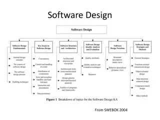
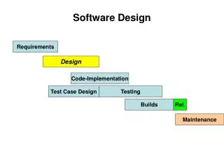
Software Design. Deriving a solution which satisfies software requirements. Phases in the Design Process. Design Phases. Architectural design: Identify sub-systems. Abstract specification: Specify sub-systems. Interface design: Describe sub-system interfaces.

Software Design
E N D
Presentation Transcript
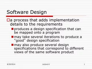
Software Design • Deriving a solution which satisfies software requirements
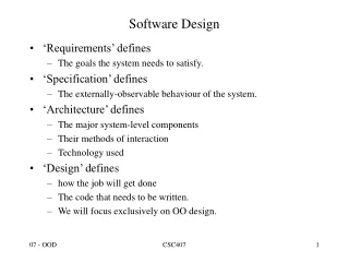
Design Phases • Architectural design: Identify sub-systems. • Abstract specification:Specify sub-systems. • Interface design:Describe sub-system interfaces. • Component design:Decompose sub-systems into components. • Data structure design: Design data structures to hold problem data. • Algorithm design: Design algorithms for problem functions.
Top-down Design • In principle, top-down design involves starting at the uppermost components in the hierarchy and working down the hierarchy level by level. • In practice, large systems design is never truly top-down. Some branches are designed before others. Designers reuse experience (and sometimes components) during the design process.
Design Methods • Structured methods are sets of notations for expressing a software design and guidelines for creating a design. • Well-known methods include Structured Design (Yourdon), and JSD (Jackson Method).
Method Components • Many methods support comparable views of a system. • A data flow view showing data transformations. • An entity-relation view describing the logical data structures. • A structural view showing system components and their interactions.
Design Description • Graphical notations: Used to display component relationships. • Informal text: Natural language description.
Design Strategies • Functional design • The system is designed from a functional viewpoint. The system state is centralized and shared between the functions operating on that state. • Object-oriented design • The system is viewed as a collection of interacting objects. The system state is decentralized and each object manages its own state. Objects may be instances of an object class and communicate by exchanging methods.
Structured Design • Introduction • Structured design was developed by Ed Yourdon and Larry Constantine. • This technique deals with the size and complexity of a program by breaking up a the program into a hierarchy of modules that result in a computer program that is easier to implement and maintain.
Structured Design • Structure Charts • The primary tool used in structured design is the structure chart. • Structure charts are used to graphically depict a modular design of a program. • Specifically, they show how the program has been partitioned into smaller more manageable modules, the hierarchy and organization of those modules, and the communication interfaces between modules. • Structure charts, however, do not show the internal procedures performed by the module or the internal data used by the module.
1 2 3 5 6 4 4 6 5 7
Structured Design • Structure Charts • Structure chart modules are depicted by named rectangles. • Structure chart modules are presumed to execute in a top-to-bottom, left-to-right sequence. • An arc shaped arrow located across a line (representing a module call) means that the module makes iterative calls. • A diamond symbol located at the bottom of a module means that the module calls one and only one of the other lower modules that are connected to the diamond. • Program modules communicate with each other through passing of data.
Structured Design • Structure Charts • Programs may also communicate with each other through passing of messages or control parameters, called flags. • Library modules are depicted on a structure chart as a rectangle containing an vertical line on each side.
Structured Design • Data Flow Diagrams of Programs • Structured design requires that data flow diagrams (DFDs) first be drawn for the program. • Processes appearing on the logical, elementary DFDs may represent modules on a structure chart. • Logical DFDs need to be revised to show more detail in order to be used by programmers • The following revisions may be necessary: • Processes appearing on the DFD should do one function. • Processes need to be added to handle data access and maintenance. • DFDs must be revised to include editing and error handling processes, and processes to implement internal controls.
Structured Design • Transform Analysis • One approach used to derive a program structure chart from program DFD is transform analysis. • Transform analysis is an examination of the DFD to divide the processes into those that perform input and editing, those that do processing or data transformation (e.g., calculations), and those that do output. • The portion consisting of processes that perform input and editing is called the afferent. • The portion consisting of processes that do actual processing or transformations of data is called the central transform. • The portion consisting of processes that do output is called the efferent.
Central Transform Afferent Efferent
Structured Design • Transform Analysis • The strategy for identifying the afferent, central transform, and efferent portions of a begins by first tracing the sequence of processing for each input. • There may be several sequences of processing. • A sequence of processing for a given input may actually split to follow different paths.
Structured Design • Transform Analysis • Once sequence paths have been identified, each sequence path is examined to identify process along that path that are afferent processes. • The steps are as follows: • Step 1 - Beginning with the input data flow, the data flow is traced through the sequence until it reaches a process that does processing (transformation of data) or an output function. • Step 2 - Beginning with an output data flow from a path, the data flow is traced backwards through connected processes until a transformation processes is reached (or a data flow is encountered that first represents output). • Step 3 - All other processes are then considered to be part of the central transform!
Structured Design • Transform Analysis • Once the DFD has been partitioned, a structure chart can be created that communicates the modular design of the program. • Step 1 - Create a process that will serve as a “commander and chief” of all other modules. • This module manages or coordinates the execution of the other program modules. • Step 2 - The last process encountered in a path that identifies afferent processes becomes a second-level module on the structure charts. • Step 3 - Beneath that module should be a module that corresponds to its preceding process on the DFD. • This would continue until all afferent processes in the sequence path are included on the structure chart.
Structured Design • Transform Analysis • Step 4 - If there is only one transformation process, it should appear as a single module directly beneath the boss module. • Otherwise, a coordinating module for the transformation processes should be created and located directly above the transformation process.. • Step 5 - A module per transformation process on the DFD should be located directly beneath the controller module.
Structured Design • Transform Analysis • Step 6 - The last process encountered in a path that identifies efferent processes becomes a second-level module on the structure chart. • Step 7 - Beneath the module (in step 6) should be a module that corresponds to the succeeding process appearing on the sequence path. • Likewise any process immediately following that process would appear as a module beneath it on the structure chart.
Structured Design • Transaction Analysis • An alternative structured design strategy for developing structure charts is called transaction analysis. • Transaction analysis is the examination of the DFD to identify processes that represent transaction centers. • A transaction center is a process that does not do actual transformation upon the incoming data (data flow); rather, it serves to route the data to two or more processes. • You can think of a transaction center as a traffic cop that directs traffic flow. • Such processes are usually easy to recognize on a DFD, because they usually appear as a process containing a single incoming data flow to two or more other processes.
Structured Design • Transaction Analysis • The primary difference between transaction analysis and transform analysis is that transaction analysis recognizes that modules can be organized around the transaction center rather than a transform center.