Download

1 / 25
250 likes | 272 Vues
Discover how to re-wire power systems correctly. Includes guidance on single-phase, two-phase, and three-phase loads. Learn to safely connect measurement transformers and use virtual ground boxes. Master the art of wiring for accurate measurements.

E N D
Wiring Power Meters Ben Kemink
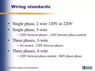
Subjects covered: • to re-wire an incorrect NEGATIVE average power situation. • to connect Single-Phase, Two-Phase , Three-Phase-Three-Three-Wire and Three-Phase-Four-Wire loads. • to connect safely measurement transformers between the loads and power meters. • more about the magic of the virtual ground box
Make a drawing i u Source Wiring Load
I + U - Positive “DC”
I - U + Negative “DC”
i + i u v ± ± - Always: First Connect the Current! Wiring Sequence
The sign of the current is positive, when the current flows from [I] terminal to [±] terminal inside the powermeter shunt. The sign of the voltage is positive when the voltage of the [V] terminal is higher than [±] terminal. i + I v ± V ± - - I v ± V ± + i Correct Connection
p Pavg v i p Pavg v i The voltage source increases and the current also
i + I V v ± ± - Incorrect Voltmeter connection The power meter displays negative value for average power. The source voltage decreases but the current increases. i v Pactive p
i + I V v ± ± - Incorrect Current meter connection v i Pactive p
Connect CURRENT METER if possible in RETURN WIRE Return wire is at lower voltage than “HOT” wire, after the voltage drop in the load.
THREE PHASE SYSTEMS Artificial Neutral Justification that Ptotal correct is with Virtual Ground Box