Download
1 / 14
170 likes | 569 Vues
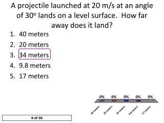
Symbols, Wiring Diagrams & Meters. N/C. N/C. N/O. N/O. Symbols. Open On Decrease. Open On Increase. Pressure Activated. Temperature Activated. If Gate Moves Towards The Symbol. If Gate Moves Away From The Symbol. Close On Increase. Close On Decrease. Symbols.

E N D
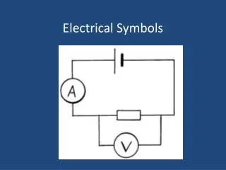
Symbols, Wiring Diagrams & Meters
N/C N/C N/O N/O Symbols Open On Decrease Open On Increase Pressure Activated Temperature Activated If Gate Moves Towards The Symbol If Gate Moves Away From The Symbol Close On Increase Close On Decrease
Symbols Automatic Reset High Temperature Limit Manual Reset Automatic Reset High Pressure Switch Manual Reset
JP- Symbols Wires Connected New Old Line Voltage Low Voltage Plug & Receptical Wires Not Connected Fuses Earth Ground Cam Switch L1 Chassis Ground L2 Mechanical Interlock Circuit Breaker (240V)
Symbols Light Emitting Diode LED Thermistor - Sensor Transformer Capacitor Resistor or electric Heating Element Multi-Speed Motor Single Speed Motor Clock Timer Motor Dual Capacitor Variable Resistor Solenoid or Gas Valve Terminal Block Thermal Overload
Symbols Thermal Relay Heater Normally Closed Contact Coil Normally Open Contact Contacts of electrically operated controls are always shown in a de-energized state Magnetic Contactor
1 Pole (Input) 1 Pole (Input) 1 Throw (output) 1 Throw (output) 2 Pole (inputs) 2 Pole (inputs) 1 Throw (output) 1 Throw (output) 1 Pole (input) 1 Pole (input) Symbols Switches or contacts are always designated as to the number of Poles (inputs) and the number of Throws (outputs ) each pole has. 1 Throw (output) 1 Throw (output) Manual Switch SPST Relay Contacts SPST Relay Contacts DPST Manual Switch DPST 1 Throw (output) 2 Throws (output) 1 Throw (output) 2 Throws (output) Relay Contacts SPDT Manual Switch SPDT
Symbols Quiz N.O. Temperature Switch N.C. Temperature Switch Closes On Temperature Increase N.C. Pressure Switch Opens On Temperature Decrease (Manual Reset) Opens On Pressure Increase N.C. Pressure Switch N.C. Temperature Switch Opens On Pressure Increase (Manual Reset) Opens On Temperature Increase N.O. Temperature Switch Closes On Temperature Decrease N.C. Pressure Switch N.C. Temperature Switch Opens On Pressure Decrease Opens On Temperature Increase
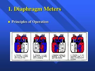
Run Capacitor Start Capacitor Compressor Contactor L1 L2 Potential Relay 240V Power Supply Ground To Thermostat High Pressure Switch Low Ambient Cutout Condenser Fan R C S L1 L2 Compressor Fuse Fuse Fuse Crankcase Heater Crankcase Heater Start Capacitor Compressor Contactor Compressor Contactor Potential Relay + Run Capacitor Compressor S C R Condenser Fan Run Capacitor Common 24V Power High Pressure Switch Low Ambient Lockout Compressor Contactor Wiring Diagram Pictorial Schematic
Pictorial Wiring Diagram Pictorial diagrams represent a snapshot of the wiring components as they actually appear when the unit access panel is removed Shows general layout of parts. Point to point wiring makes makes field wiring easy. Easy to count the wires the installer needs to run. Many wires tend to become crossed making it confusing to use for trouble shooting. Pictorial representation of components may not show the actual function of the component.
Compressor Contactor Compressor Run Capacitor Compressor Start Capacitor Potential Relay 2 L1 L2 240V Power Supply 6 1 Condenser Fan Run Capacitor R High Pressure Limit Condenser Fan R C S C S Compressor To Thermostat Crankcase Heater Low Ambient Cutout Pictorial Wiring Diagram Run Capacitor Start Capacitor Compressor Contactor L1 L2 Potential Relay 240V Power Supply Ground To Thermostat High Pressure Switch Low Ambient Cutout Condenser Fan Compressor Crankcase Heater
Schematic Wiring Diagram Schematic or Ladder diagrams use graphical symbols to show electrical components instead of pictorial representations. Graphical symbols are used to represent the separate parts of each component. Easy to trace circuits for troubleshooting. Each symbol represents a specific function making it easier to determine the operating sequence. Wires do not cross. This makes it easy to trace circuits. Since components are split into their constituent parts, it is difficult to determine where field wiring should be connected. It may be difficult to locate all constituent parts of a component.
1 2 5 C S R Compressor Contactor Schematic Wiring Diagram L1 L2 Fuse Fuse Fuse Crankcase Heater Start Capacitor Compressor Contactor Compressor Contactor Potential Relay 1 2 5 + Compressor Run Capacitor Condenser Fan Run Capacitor Common 24V Power High Pressure Switch Low Ambient Lockout Compressor Contactor
RMS 170v 120v RMS 0v 120v RMS 170v ROOT MEAN SQUARE