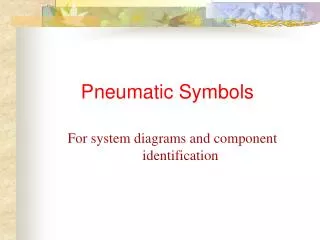
Pneumatic Symbols
Pneumatic Symbols. For system diagrams and component identification. Standards. Actuators. Contents. Basic symbols. Valve symbol structure. Functional elements. Valve functions. Flowlines. Three position valves. Connections. Operators. Conditioners and plant. Port marking.

Pneumatic Symbols
E N D
Presentation Transcript
Pneumatic Symbols For system diagrams and component identification
Standards Actuators Contents • Basic symbols • Valve symbol structure • Functional elements • Valve functions • Flowlines • Three position valves • Connections • Operators • Conditioners and plant • Port marking • Pressure regulators • Function components • Relief valves • Symbol Library Click the section to advance directly to it
Graphic Symbols Standards • Pneumatic symbols conform to and are devised from the International Standard ISO 1219-1 1991 • This covers graphical symbols for Fluid Power Systems and Components • Port markings for fluid power valves are not covered by the ISO standard. These are taken from the recommendations of CETOP RP 68 P
Shapes • These shapes and lines in the relative proportions shown, make up a set of basic symbols from which fluid power symbols and circuits are constructed
Basic Symbols (shapes) • Symbol sets can be drawn to any size but their scale and relative proportions are determined by a basic dimension of your choice “l” Circles energy conversion units l l measuring instrument 3/4 mechanical link l 1/3 roller l 1/3
l Basic Symbols (shapes) l Square control component connections perpendicular to sides conditioning apparatus connections to corners Square at 45o > l l Rectangle cylinders and valves
Basic Symbols (shapes) 1/4l Rectangles piston l continued 1/4l cushion 1/2l min 1 l certain control methods, length between limits to suit 1/2l 1/2l max 2l
Basic Symbols rotary actuator, motor or pump with limited angle of rotation l Semi-circle 2l pressurised reservoir air receiver, auxiliary gas bottle Capsule l mechanical connection piston rod, lever, shaft Double line 1/5 l
Basic Symbols 2 12 10 Working line, pilot supply, return, electrical Line 3 1 Dashed Pilot control, bleed, filter Chain Enclosure of two or more functions in one unit Line Electrical line
1/4l Functional Elements 1/2l Triangle Direction and nature of fluid, open pneumatic or filled hydraulic Spring size to suit Arrow Long sloping indicates adjustability 1/3l
Functional Elements Arrows Straight or sloping path and flow direction, or motion Tee Closed path or port Restriction Size to suit
Functional Elements Curved arrows rotary motion Shaft rotation clockwise from right hand end anti-clockwise from right hand end both Seating 90o angle
Functional Elements Temperature Indication or control size to suit Operator Opposed solenoid windings M Prime mover Electric motor M
Flowlines Junction Single Junction Four way junction not connected Crossing Hose usually connecting parts with relative movement Flexible line
Connections Air bleed Continuous Temporary by probe Air exhaust No means of connection With means of connection
Connections Coupling quick release Both to exhaust Coupling quick release self sealing Source sealed Coupling quick release self sealing Both sealed
Connections Rotary connection one line Rotary connection two lines Rotary connection three lines
Conditioners • Water separator with manual drain • Water separator with automatic drain • Filter with manual drain • Filter with automatic drain • Lubricator
Conditioners • Dryer • Cooler with and without coolant flow lines • Heater • Combined heater / cooler
M Plant • Compressor and electric motor • Air receiver • Isolating valve • Air inlet filter
Pressure regulators • A pressure regulator symbol represents a normal state with the spring holding the regulator valve open to connect the supply to the outlet. • The dotted line represents the feedback, this opposes the spring and can vary the flow through the valve from full flow, through shut off, to exhaust. The symbol is usually drawn in only this one state. The flow path can be imagined to hinge at the right hand end to first shut off the supply then connect to the exhaust. • Adjustable Regulator simplified • Adjustable Regulator with pressure gauge simplified
Filter Regulator Lubricator • FRL Combined unit • FRL Simplified symbol
Pressure relief valves • A pressure relief valve symbol represents a normal state with the spring holding the valve closed. • The dotted line represents feed-forward, this opposes the spring and can be imagined to lift the flow path. When the pressure reaches an excess value the flow path will line up with the ports and flow air to relief. • Adjustable relief valve simplified • Preset relief valve simplified
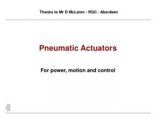
“l” Actuators • Cylinders symbols can be any length over “l” • The piston and rod can be shown in the retracted, extended or any intermediate position
Single acting • Single acting sprung instroked • Single acting sprung outstroked • Single acting sprung instroked magnetic * • Single acting sprung outstroked magnetic * * ISO 1219-1 provides no example for magnetic cylinders
Single acting without spring • Single acting normally instroked external force returns • Single acting normally outstroked external force returns • Single acting normally instroked magnetic external force returns • Single acting normally outstroked magnetic external force returns Note: the hardware is usually double acting cylinders applied as single acting
Double acting • Double acting adjustable cushions • Double acting through rod • Double acting magnetic * • Double acting rodless * * ISO 1219-1 provides no example for magnetic or rodless cylinders
Rotary actuators • Semi rotary double acting • Rotary motor single direction of rotation • Rotary motor bi-directional
Simplified cylinder symbols • Single acting load returns • Single acting spring returns • Double acting non cushioned • Double acting adjustable cushions • Double acting through rod
Valve symbol structure • The function of a valve is given by a pair of numerals separated by a stroke, e.g. 3/2.. • The first numeral indicates the number of main ports. These are inlets, outlets and exhausts but excludes signal ports and external pilot feeds. • The second numeral indicates the number of states the valve can achieve.
Valve symbol structure • A 3/2 valve therefore has 3 ports (normally these are inlet, outlet and exhaust) and 2 states (the normal state and the operated state) • The boxes are two pictures of the same valve operated normal
Valve symbol structure • A valve symbol shows the pictures for each of the valve states joined end to end operated normal
Valve symbol structure • A valve symbol shows the pictures for each of the valve states joined end to end operated normal
Valve symbol structure • The port connections are shown to only one of the diagrams to indicate the prevailing state normal
Valve symbol structure • The operator for a particular state is illustrated against that state Operated state produced by pushing a button
Valve symbol structure • The operator for a particular state is illustrated against that state Operated state produced by pushing a button Normal state produced by a spring
Valve symbol structure • The operator for a particular state is illustrated against that state Operated state produced by pushing a button Normal state produced by a spring
Valve symbol structure • The valve symbol can be visualised as moving to align one state or another with the port connections
Valve symbol structure • The valve symbol can be visualised as moving to align one state or another with the port connections
Valve symbol structure • The valve symbol can be visualised as moving to align one state or another with the port connections
Valve symbol structure • A 5/2 valve symbol is constructed in a similar way. A picture of the valve flow paths for each of the two states is shown by the two boxes. The 5 ports are normally an inlet, 2 outlets and 2 exhausts
Valve symbol structure • The full symbol is then made by joining the two boxes and adding operators. The connections are shown against only the prevailing state
Valve symbol structure • The full symbol is then made by joining the two boxes and adding operators. The connections are shown against only the prevailing state