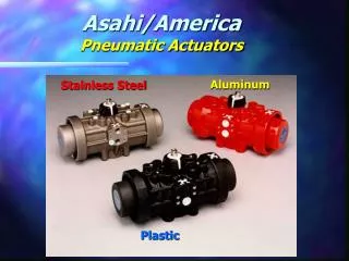
Pneumatic Actuators
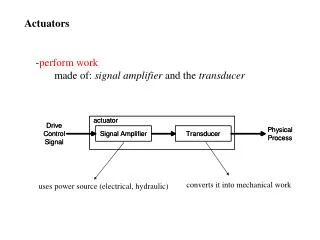
Thanks to Mr D McLaren - RGC - Aberdeen. Pneumatic Actuators. For power, motion and control. Introduction. Pneumatic actuators include linear cylinders and rotary actuators. They are devices providing power and motion to automated systems, machines and processes.

Pneumatic Actuators
E N D
Presentation Transcript
Thanks to Mr D McLaren - RGC - Aberdeen Pneumatic Actuators For power, motion and control
Introduction • Pneumatic actuators include linear cylinders and rotary actuators. • They are devices providing power and motion to automated systems, machines and processes. • A pneumatic cylinder is a simple, low cost, easy to install device that is ideal for producing powerful linear movement. • Speed can be adjusted over a wide range. • A cylinder can be stalled without damage.
Introduction • Adverse conditions can be easily tolerated such as high humidity, dry and dusty environments and cleaning down with a hose. • The bore of a cylinder determines the maximum force that it can exert. • The stroke of a cylinder determines the maximum linear movement that it can produce. • The maximum working pressure depends on the cylinder design. School cylinders work up to 9 bar. • Thrust is controllable through a pressure regulator.
Basic Construction 1 cushion seal 2 magnet 3 cushion sleeve 4 barrel 5 guide bush 6 rod and wiper seal 7 front end cover 8 front port 9 reed switch 10 piston rod 11 wear ring 12 piston seal 13 rear end cover 14 cushion screw
Fundamental designs • Pneumatic actuators are made in a wide variety of sizes, styles and types including the following • Single acting with and without spring return • Double acting • Non cushioned and fixed cushioned • Adjustable cushioned • Magnetic • Rodless • Rotary • Clamping • Bellows
Single acting spring return • Single acting cylinders have a power stroke in one direction only • Normally in • Normally out Click the illustrations to start and stop animation
Double acting • Double acting cylinders use compressed air to power both the outstroke and instroke. • Superior speed control is possible • There are • Non-cushioned types • Fixed cushioned types • Adjustable cushioned types
Double acting non-cushioned • Non cushioned cylinders are suitable for full stroke working at slow speed. • Higher speeds with external cushions Click the illustration to start and stop animation
Cylinder sizing for thrust • The theoretical thrust (outstroke) or pull (instroke) of a cylinder is calculated by multiplying the effective area of the piston by the working pressure. • The effective area for thrust is the full area of the cylinder bore “D”. • The effective area for pull is reduced by the cross section area of the piston rod diameter “d”. D d
2 D P Thrust F Newtons = 4 10 Cylinder sizing for thrust • In the formula, P is divided by 10 to convert bar to Newtons per square millimetre (1 bar = 0.1 N/mm2) Where D = Cylinder bore in millimetres P = Pressure in bar F = Thrust or Pull in Newtons
2 2 ( D d ) P - Pull F Newtons = 40 Where D = Cylinder bore in millimetres d = Piston rod diameter in millimetres P = Pressure in bar F = Thrust or Pull in Newtons Cylinder sizing for thrust • Pulling force F will be less than the thrust due to the area lost to the piston rod
Speed control • The maximum natural speed of a cylinder is determined by: • the cylinder size, • the ports size, • inlet and exhaust valve flow, • the air pressure, • the bore and length of the hoses, • the load against which the cylinder is working.
Speed control • From the natural speed it is possible to increase or reduce it. • Normally a smaller valve reduces cylinder speed. • A larger valve might increase cylinder speed. • A limiting factor will be the aperture in the cylinder ports restricted aperture unrestricted aperture
Speed control • Once a valve, cylinder, pressure and load are selected, adjustable speed control is effected with flow regulators. • Speed is regulated by controlling the flow of air to exhaust • The front port regulator controls the outstroke speed and the rear port regulator controls the instroke speed.
Flow regulator • Uni-directional, line mounted adjustable flow regulator • Free flow in one direction • Adjustable restricted flow in the other direction
Banjo flow regulator • Designed to fit directly in to the cylinder port, so placing adjustment at the appropriate cylinder end. Select the type to give conventional flow restriction out of the cylinder and free flow in.
Increasing speed • In some applications cylinder speed can be increased by 50% when using a quick exhaust valve. • When operated, air from the front of the cylinder exhausts directly through the quick exhaust valve. • Built in cushioning will be less effective.
Quick exhaust valve • Air flows from the control valve in to the cylinder past a poppet lip seal. • When the control valve is operated the falling pressure from the valve allows the poppet seal to snap open. • The air in the cylinder rapidly exhausts through the large exhaust port and silencer. 2 1 2 2 1 1