Download
1 / 72
760 likes | 1.04k Vues
Learn about pneumatic actuators, gas laws, power cylinders, types of actuators, and Festo Copac linear actuator in this comprehensive guide.

E N D
Hydraulic and Pneumatic Actuators and their Application Areas Elena Ponomareva JASS 2006 – St. Petersburg
Introduction Figure A. Automatic Pneumatic Drive: UGM -units of gas networks and mains; PA - pneumatic amplifiers; PE - pneumatic engines; MT - the mechanism of transfer; CSD -converting and summing device; ACE - amplifiers of capacity of electric signals; EMC - electromechanical converters; DF - devices of feedbacks; AC - adjusting circuits; IF - internal feedbacks; GG -a source of gas energy
Gas Laws Boltzmann’s equation • The strings and are the Kinetic Energy • m refers to the mass of one atom • < c2 > refers to the average of c2 • k refers to the Boltzmann constant • T refers to the temperature of the surroundings The combined gas law The ideal gas law • P is the pressure in atmospheres (atm) or kilopascals (kPa); • V is the volume in liters • n is the number of moles of gas • R is the ideal gas constant in L atm/mol K or Pa m³/mol K • T is the temperature in kelvins.
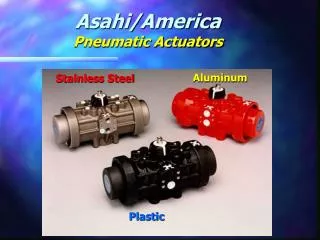
Classification Of Pneumatic Actuators All pneumatic actuators can be subdivided into the following types: diaphragm pneumatic actuators; pneumatic power cylinders; gas-engine pneumatic actuators; turbine pneumatic actuators; jet pneumatic actuators; pneumomuscles; combined pneumatic actuators.
Diaphragm Pneumatic Actuators Figure 1.1. The membrane pneumatic actuator: 1 - the connecting pipe of the second cavity; 2 - the connecting pipe of the first cavity; 3 - the membrane; 4 - the case; 5 - the rod; G1 - the second charge of a gas stream in the first cavity; G2-the second charge of a gas stream in the second cavity; p1 - pressure of gas in the first cavity; р2 - pressure of gas in the second cavity; xr - moving of the rod Figure 1.2. The sylphon pneumatic actuator: 1 - the connecting pipe of the second cavity; 2 - the connecting pipe of the first cavity; 3 - the case; 4 — the rod with the piston of the first cavity; 5 - a sylphon of the first cavity; 6 – the closing up of the sylphon of the first cavity
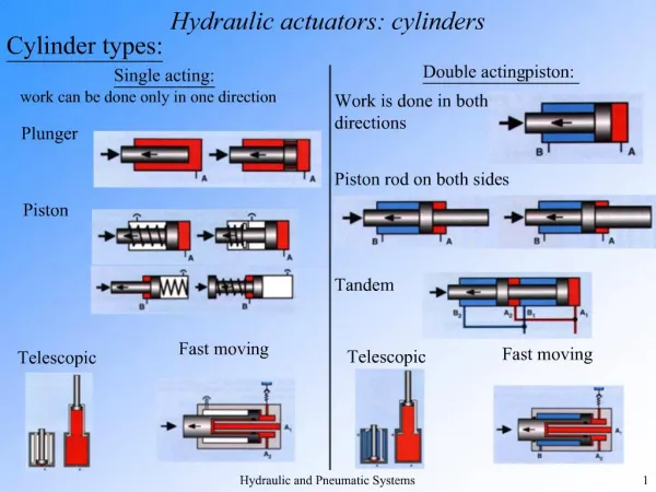
Pneumatic Power Cylinders As compressed air moves into the cylinder, it pushes the piston along the length of the cylinder. Compressed air or the spring, located at the rod end of the cylinder, pushes the piston back.
Pneumatic Power Cylinders A double acting pneumatic cylinder has two- directed powered motion, with pressure on both sides.
Pneumatic Power Cylinders • Optimal range • Good running performance and long service life thanks to smooth, hard cylinder bore • Piston rod and cylinder barrel made of stainless steel • More than the standard • Round cylinders with piston diameters from 8 to 25 mm conform to ISO 6432, DIN ISO 6432. Variants are based on these standards. The series is not repairable. • The cap is swaged onto the barrel. • Functional • Three different end caps mean numerous functional and spacesaving designs • Variants • Non-rotating • Through piston rod • With or without position sensing • Cushioning non-adjustable at either end or cushioning adjustable at both ends • Further piston rod variants
Pneumatic Power Cylinders Double-acting double-rod cylinder – double-acting cylinder with a piston rod extending form each end. The piston rods are connected with the same piston. Double-rod cylinders provide equal force and speed in both directions.
Pneumatic Power Cylinders • Fast or slow valve actuation • Position sensing • Internal air channels eliminate protruding tubing and attachments, and thus also harmful accumulation of contaminants • Suitable for manual on-site use, as well as automatic operation • Opening and closing actuated via flange-mounted solenoid valve with port pattern to Namur, or via valve terminals with a choice of 30 different fieldbus protocols • Sturdy and reliable, even in aggressive environments • Highly corrosion resistant Festo Copac Linear Actuator
Pneumatic Power Cylinders Ideal for vertical use • Ball-bearing circulatingguide system for a longservice life whenoperatedvertically • Double piston rod for a highlevel of force in spite of a flat design • Compactdimensions • Symmetric geometry • Low weight • Wide variety of mountingoptions The ZSC series is available in five sizes with piston diameters of 6 to 25 mm and strokes from 10 to 100 mm (in 10 mm increments). The mini slides operate at a speed between 0.05 to 0.5 m/s (0.16 to 1.6 ft/s) at an operating pressure of 1.5 to 7 bar (22 to 102 psi).
Pneumatic Power Cylinders The GPC series is ideal for all applications that demand absolute precision and side load capacity. Compared to standard cylinders, cylinders from this series offer extremely precise movement, high side load capacities, and also torsion protection. This results in fewer outer guides to design and set up machines.
Pneumatic Power Cylinders Tandem cylinders ADVUT • A maximum of 4 cylinders can be combined. • The internal distribution of compressed air means that only 2 connections are required to pressurise all cylinders. • The force in the return stroke corresponds to that of a single cylinder with corresponding piston diameter. By connecting 2, 3 or 4 cylinders with the same piston diameter and stroke in series, the force in the advance stroke (thrust) can be doubled, tripled or quadrupled in comparison to a single cylinder.
Pneumatic Power Cylinders Shock influence is required in a number of technological operations, such as punching, marking, punching of holes. In this case we useshot pneumocylinders. Figure 1.3. The scheme of the shot pneumocylinder: A, b, c – cavities; 1, 3, 4 – channels; 2 - aperture
Pneumatic Power Cylinders In technological operations when the executive mechanism is, for example, the cutting tool or a gearshift, it is necessary to establish two and more fixed positions, multiposition pneumocylinders or pneumatic positioners are used. Figure 1.4. Threeposition pneumocylinder: A, B, C -control valves; 1, 2, 3 –channels; T1, T2 –pneumothrottles; a, b – cavities; Рip- pressureof compressed air in cavities a and b
Pneumatic Power Cylinders • All settings accessible from one side: • Precision end-position adjustment • Position of proximity sensors • Mounting of drive • Speed regulation • Pneumatic end-positioncushioning • Sealing system • Compact – fitting length relative to stroke • Loads and devices can be directly mounted on the slide
Pneumatic Power Cylinders Figure 1.5. The hose pneumocylinder: 1 – hose; 2 - rollers of the carriage; 3 - control valve; B
Pneumatic Power Cylinders • Nominal swivel angles of 90°, 180°, 270° or 360° • Freely selectable swivel angle from 0 to 360° • With adjustable end-position cushioning at both ends and end-position adjustment for piston ∅ 16 to 100 mm • With adjustable end-position cushioning at both ends for piston ∅ 40 to 100 mm Figure 1.6 Rotary pneumoactuator: 1, 2, 5 - channel; 3 - piston; 4 - chain transfer; A - cavity;Рip - pressure • For contactless position sensing • Backlash-free power transmission • Wide choice of mounting options
Pneumatic Power Cylinders Figure 1.7 Chamber rotary pneumoactuator: 1 – channel; 2 - chamber; 3, 4 – levers; 5 - detail
Pneumatic Power Cylinders The pneumomotor with the limited angle of turn is applied to perform oscillating movements of the output shaft or its rotation on the definite angle. Figure 1.8 The pneumomotor with the limited angle of turn: 1 - case; 2 - blade: 3 - target shaft; 4 - compaction; 5, 6 - fittings; 7 - stops
Pneumatic Power Cylinders Figure 1.9 Lateral force Fq as a function of stroke length l.
Pneumatic Power Cylinders Figure 1.10 Pneumomuscle: 1 - internal elastic tube;2 - braid; 3, 4 – covers;5 – feeding channel Figure 1.12 Geometrical parametersof reduced pneumomuscles: 1 - braid; 2 - internal elastic tube; 3 – pantograph’s cell Figure 1.11 Comparative characteristics of output efforts of the power cylinder and the pneumomuscle: 1 - power cylinder; 2 - pneumomuscle
Pneumatic Power Cylinders Figure 1.13 The artificial muscle: 1 – casing; 2 - elastic tube; 3 – thermoelement; 4 – filler; 5 - electric leading-out wires
Pneumatic Power Cylinders Figure 1.14 The electropneumatic actuator: 1 - amplifier of direct current; 2 - electromechanical converter; 3 - choker; 4 - nozzles, 5 - throttles, 6, 7 - executive pneumocylinders, 8, 9 - feedback sensors 10 - spring, 11 - flywheel
Advantages and disadvantages • Disadvantages: • compressibility of the air • impossibility to receive uniform and constant speed of the working bodies movement • difficulties in performance at slow speed • limited conditions – use of compressed air is beneficial up to the definite values of pressure (the cost of compressed air productior increases sharply when the pressure in the system exceeds 8…10 bar) • compressed air requires good preparation (the air should be cleared of mechanical impurity and should be free of moisture) • Advantages: • simplicity of realization relatively to small back and forth motions; • sophisticated transfer mechanisms are not required • low cost • high speed of moving • ease at reversion movements • tolerance to overloads, up to a full stop. • high reliability of work • explosion and fire safety • ecological purity • ability to accumulation and transportation
The original formof Bernoulli's equation v = fluid velocity along the streamline g = acceleration due to gravity on Earth h = height from an arbitrary point in the direction of gravity p = pressure along the streamline ρ = fluid density The second, more general form of Bernoulli's equation φ is the gravitational potential energy per unit mass ω is the fluid enthalpy per unit mass εis the fluid thermodynamic energy per unit mass Bernoulli's Equation
The Structure of Hydraulic Cylinders Figure 2.1. The hydraulic cylinder:a - one- sided action with a returnable spring;b— double-sided action controlled by the differential scheme;1 — plunger;2 — spring;3 — basic sealant;4 — antisplash sealant; 5 — piston;6 — nternal sealant; 7 — rod;8 — a basic external sealant;9 — antisplash external sealant;10 — rod’s cavity;11 — supply circuit; I, II — positions of a control valve;F — external force;S— the full area of the piston;S' - the ring area of the piston;Q, q —submission and plums of a stream accordingly
The Structure of Hydraulic Cylinders Figure 2.2. The hydraulic cylinder with a double-sided rod: a - with the fixed rod; b — with the fixed hydraulic cylinder and a control valve; 1—internal consolidation; 2, 5 — antisplash external consolidations; 3, 4 — basic external consolidations; F - external force; h — course of the piston; p1, р1' — low pressure; p2, р2' — high pressure; Q — the charge; v — speed of the piston
The Structure of Hydraulic Cylinders Figure 2.3. The three-high-speed hydraulic cylinder: 1,3, 6 — hydrolines; 2 — the internal hydraulic cylinder; 4, 5 — cavities; F— external force; S1 - area of the hydraulic cylinder 2; S2, S3- area of cavities 5 and 4 accordingly
The Structure of Hydraulic Cylinders Figure 2.4. The telescopic hydraulic cylinder: 1,6-pistons; 2, 3 — cavities; 4 — sleeve; 5 — hydroline; 7 — supply; F- the external force; S1. S2 —the area of cylinders with pistons 1 and 6 accordingly; S3, S4- areas of cavities 2 and 3 accordingly
The Structure of Hydraulic Cylinders Figure 2.5. The hydraulic cylinder with trailer throttle brakes and the protected rod: 1 - throttle; 2,3 - sockets; 4 — rubber sylphon; 5 — return valves; 6,7- ledges of the piston; 8 — ring volume; other designations see on fig. 2.2
The Structure of Hydraulic Cylinders Figure 2.6. The piston of the hydraulic cylinder with fixing devices: 1 - sealant element; 2 — conic surface; 3 — ball; 4 — spring; 5, 7 — cavities of the hydraulic cylinder; 6 — piston
The Structure of Hydraulic Cylinders Figure 2.7. Consolidation of rods (a, b) and pistons (c, d) of hydrocylinders: a – with a round rubber ring; b,c – with V-look cuffs; d — with a bilateral cuff; 1 — aprotective ring; 2 — plastic persistent ring; 3 — rubber ring; 4 — nut; 5— dividing plastic cuff; 6 — consolidating rubber cuff; 7 — directing belt of a cuff; 8— cuff; 9 — bilateral cuff
Volumetric Hydraulic Actuator Figure 2.8. Hydraulic Jack In this system , areservoir and a system of valves has been added to a simple hydraulic lever to stroke a small cylinder or pump continuously and raise a large piston or an actuator a notch with each stroke.
Volumetric Hydraulic Actuator Figure 2.9. Basic schemes of a hydraulic actuator: a - forward movement; b — rotary movement; c — hydromotor; 1 — hydraulic engine; 2 — hydraulic control valve; 3 — hydrotank; 4 — adjustable pump; 5 — safety valve; F — working force
Volumetric Hydraulic Actuator Figure 2.10. The scheme of a hydraulic actuator with the closed circulation of a liquid: 1 - adjustable pump; 2— auxiliary pump; 3 — downflow flap; 4 — return flap; 5— safety flaps; 6 — hydraulic engine (adjustable hydromotor); a, b — hydrolines
Volumetric Hydraulic Actuator Figure 2.11. The scheme of a hydraulic actuator with a regulator of a stream: 1— regulator; 2 — adjustable throttle; 3 — reducing valve; Рth - pressure in a throttle upon an input; Рp - pressure of the pump
Volumetric Hydraulic Actuator Figure 2.12. The scheme of a hydraulic actuator with steady output rotation frequency: 1 - a pump; 2 — a hydromotor; 3 — the shaft of the hydromotor; 4 — a centrifugal regulator; 5 — the valve of the hydraulic control valve ; 6 — the hydrocylinder; 7 — a disk
Volumetric Hydraulic Actuator Figure 2.13 The scheme of a stream divider:1 — throttles; 2, 3 — apertures; 4 — a piston; 5 — a sleeve; M — a point of division of stream Q on streams Q1, and Q2
Follower Hydraulic Actuator Figure 2.14 The scheme of a follower hydraulic actuator of cross-section submission of a support of the copy machine tool: 1 - piston; 2 — cavity; 3 — hydraulic control valve; 4 — bringing hydroline; 5 —probe; 6 — master cam; 7 — the case of the hydraulic cylinder; 8 — the case of the support; 9 — support Figure 2.15 The scheme of the hydraulic booster with a mechanical feedback:: 1 - point (hinge); 2—draft; 3 — piston; 4 — power cylinder; 5 — hydraulic control valve; 6 — rod (an output link); 7 — a point of an output link; 8 — differential lever; n, m – links of a double-shouldered lever
Advantages and Disadvantages • Variable hydraulic actuators are widely used as drives of machine tools, rolling mills, pressing and the foundry equipment, road and building machines, transport and agricultural machines, etc. A number of advantages in comparison with mechanical and electric transfers explains such their wide application: • infinitely variable control of gear-ratio in a wide range and an opportunity to create the big reduction ratio; • small specific weight, i.e. the weight of a hydroactuator is in ratio to transmitted capacity (0,2...0,3 kg / kWt); • opportunity of simple and reliable protection of the engine from overloads; • small sluggishness of the rotating parts, providing fast change of operating modes (start-up, dispersal, a reverser, a stop); • simplicity of transformation of rotary movement into reciprocating one; • opportunity of positioning a hydraulic engine on removal(distance) from an energy source and freedom in making configuration. • It is also necessary to reckon with disadvantages of hydraulic actuators: • Efficiency of a volumetric hydraulic actuator is a little bit lower, than efficiency of mechanical and electric transfers, and during regulation it is reduced; • conditions of operation of a hydraulic actuator (temperature) influence its characteristics; • Efficiency of a hydraulic actuator is a little reduced in the process of exhaustion of its resource owing to the increase in backlashes and the increase of outflow of liquid (falling of volumetric efficiency); • sensitivity to pollution of working liquid and necessity of high culture service.
Some More Cylinders Multi-position cylinder
Some More Cylinders Linear/swivel clamp CLR