PNEUMATIC SYSTEMS
PNEUMATIC SYSTEMS. PNEUMATIC SYSTEM.

PNEUMATIC SYSTEMS
E N D
Presentation Transcript
PNEUMATIC SYSTEM • The learning objective of this presentation, To develop the student's knowledge of the vacuum system to meet the basic functions in vacuum system that supply essential instruments of the aircraft and ability to detect abnormal or unsafe operation and responding to a vacuum system failure
PNEUMATIC SYSTEM • Aircraft Pneumatic System Intro • Vacuum Systems • Pneumatic Use in Small Aircraft • Pneumatic System Components • Air Pumps • Pneumatic System Operation • Actions before every flight • Failure Causes • Early Recognition • Emergency Procedures • Spatial Disorientation • Redundancy Options
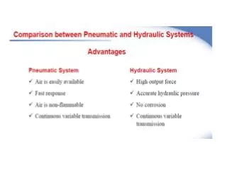
Aircraft Pneumatic System Intro • Sometimes called vacuum pressure systems • Aircraft Pneumatic Systems power Instruments, *landing gear, *flaps, air conditioning, windows, doors and more • In light Aircraft, Suction Pressure Gauge shows Vacuum System Pressure
Vacuum Systems • Pumps • Relief Valves • Vacuum Air Filter • Suction Gauge Gyro instruments: - Attitude Indicator - Heading Indicator
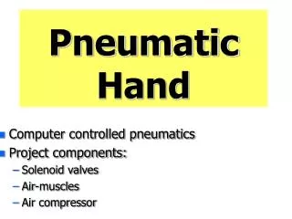
Pneumatics Use in Small Aircraft • Gyro compass • Artificial Horizon • Turn coordinator
Pneumatic System Components •Air Pump •Vacuum Regulator •Inlet Air Filter •Overboard Vent Line •Gauges: – Attitude Indicator – Heading Indicator •System Indicators – Suction Gauge – Gyro Flag – Annunciator Lights
Pneumatic System Components • Pneumatic Air Filter • Prevents system contamination • Remove air particulates • Clean air is essential to good operation
Pneumatic System Components • Pneumatic Pressure Regulator • - Prevents System over pressurization • - Insures proper calibration
Air Pump Heart of pneumatic system is pressure or vacuum air pump (Usually engine driven) • Two basic types : • Wet air pumps use engine oil to lubricate pump internally • Dry air pumps - more common –have graphite vanes inside pump casing - self-lubricate as pump rotates
Pneumatic System Operation •Filtered Air is pulled through system by vacuum pump •Evacuated air passes through instrument case causes gyro to spin •Spinning gyros provide “rigidity in space” for instrument references •Air exhausts through Gyro Pressure Gauge exhaust port – Gauge measures system pressure •Failure Warning Systems
Actions Before Every Flight Check for oil leaks Check the hose And clamps for Oil leaks Check for loose fittings that allow contaminants into the system Check for external damage
Failure Causes • System Contamination • - Solid particles in pneumatic • system damage pump • and plug valve openings • – Liquids from oil, water, or engine • cleaning solvents • Restriction/ leaks within the system • -A loose fitting or damaged hoses • -Worn out, misused, or incorrectly • routed hoses • Sudden changes in engine speed • - Abrupt engine deceleration • - Sudden engine stoppage
Early Recognition • Pneumatic System health can be determined by the indications on either the vacuum gauge or flags on the attitude indicator
Early Recognition • Inaccurate/conflicting Instrument information • Suction/pressure gauge indicates outside normal operating (green) range • Spotting pneumatic system failure early reduces chances of spatial disorientation
Statistics 95% are Fatal 5% non Fatal • While pneumatic system failures alone do not cause accidents, spatial disorientation does, and tragically these accidents are almost always fatal
Spatial Disorientation Accidents byPilot Certificate and Weather Conditions
Emergency Procedures • Activate a back up power supply for pneumatics ( aux Vacuum pump if have) • Maintain partial panel instrument flying • - Cover up or simulate loss of flight instruments • Make timed turns • Notify ATC • In IMC –seek and fly VMC
Spatial Disorientation When your instruments disagree, confusion, dizziness, and uncertainly can cause loss of control. Spatial disorientation occurs quickly when outside visual reference is poor such as night, IMC , Haze
Redundancy Options • Electrical Power Instruments • Secondary Air pump ( Electric Aux Vacuum Pump) • Pressure differential Switch
Conclusion • Pneumatic Systems fail at unexpected times • The danger , in the event of pneumatic system failure is spatial disorientation • Have a good knowledge what power systems on the aircraft you fly • Practice on the partial panel Flying and be familiar with aircraft instruments • Whether you rent, own, or operate become familiar with the maintenance history of the Aircraft