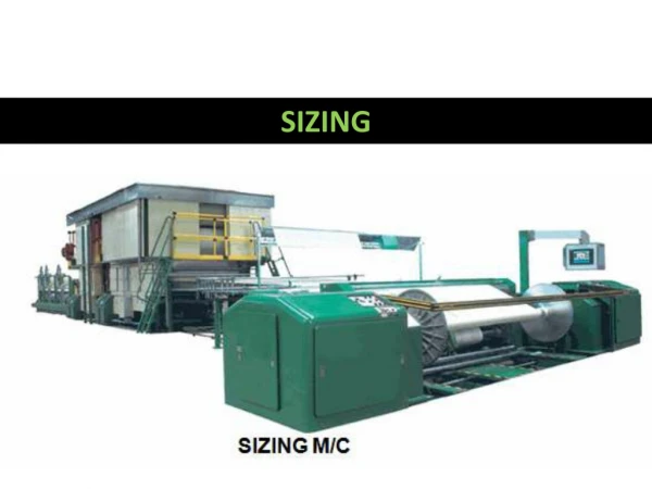
SIZING PNEUMATIC SYSTEMS
SIZING PNEUMATIC SYSTEMS. Introduction. Pneumatic systems are sized to meet output power requirements. The air distribution system is sized to carry the required air flow with minimum friction losses through sections of pipe and various fittings.


SIZING PNEUMATIC SYSTEMS
E N D
Presentation Transcript
Introduction • Pneumatic systems are sized to meet output power requirements. • The air distribution system is sized to carry the required air flow with minimum friction losses through sections of pipe and various fittings. • the compressor and receiver are sized as one unit • Pneumatic valves are used to regulate the pressure, air velocity, and flow rate, and to manage the direction of flow. • Cylinders are sized to meet the demand of the load resistance . The bore is determined from the force requirement and the stroke from the length of travel.
Pressure Pressure is defined as the force exerted by a fluid per unit area. Units in SI are Pa=N/m2. The pressure unit Pascal is too small for pressure encountered in practice. Therefore, kPa and MPa are commonly used. Units in British are : psf = lbf/ft2, psi = lbf/in2 You have to convert from psi to psf ( 144 in2 = 1 ft2)
Pressure (Continued) Absolute pressure, is measured relative to absolute vacuum (i.e., absolute zero pressure.) Gauge pressure, is measured relative to atmospheric pressure
Fluid Flow in Pipes • Laminar (Re below 2000) • Flow is consistent and streamline • Turbulent (Re above 4000) • Flow is mixed up and disorganized • However, there is a range where the fluid is neither laminar nor turbulent • (2000 < Re < 4000)
Friction Losses PNEUMATIC DISTRIBUTION SYSTEMS
PNEUMATIC DISTRIBUTION SYSTEMS Air systems are plumbed to minimize losses between the receiver located near the compressor and the point of use. A loss of 10% pressure is allowable under normal operating conditions with less than half the loss being attributed to the main transmission line. Loop systems provide air through more than one path to the air drops, thereby reducing run length restrictions. Where loops are particularly long, installing more than one compressor at convenient locations reduces the run length and resulting pressure drop. Provision also is made to pitch air lines slightly from 0.1- .25 in./ft, to collect moisture accumulation in lines at drain points where water can be removed periodically.
Types of Losses • Major losses are calculated directly using the overall length • Minor losses are converted into equivalent piping (straight) lengths then calculated using the Major losses formula. • Major Losses: Pipes, hoses, and tubing • Minor Losses: Valves, fittings, bends, enlargements/contractions, and orifices
Harris Formula • Pressure losses in transmission lines can be calculated using the Harris formula, or convenient tables. • From the Harris formula, pressure loss due to friction (Pf) is computed from
pressure drop • Where • Pf= pressure drop due to friction (psi) • L = length of pipe (ft) • Q = ft3/ sec of free air • CR = ratio of compression at the pipe entrance • d = actual internal diameter of the pipe (in.) • C = experimental coefficient
CALCULATED VALUES FOR d 5.31 FOR SCHEDULE 40 PIPE SIZES
The friction loss through fittings is determined for each size and type of fitting experimentally, and expressed as an equivalent length of straight pipe of the same size. • The equivalent length s of all fittings in the system then are added together and combined with the length term in the Harris formula to determine the pressure drop for the system. • The friction loss for a number of common fittings of various sizes is given in Table 16-2. (equivalent length) • It should be noticed that for any particular fitting the equivalent • length increases dramatically with pipe size.
COMPRESSORS Air compressors are sized to supply present equipment, with a 25%-50% capacity built in for future expansion. First the pressure range is selected , usually 80 to 140 lbf/in ", Then the free air demands of all tools and equipment using the air are totaled-both the continuous demand and the average air demand. The continuous demand is the amount of air required if all the air tools and equipment were operated continuously; whereas the average demand is the free air consumption rate multiplied by the percentage of time the equipment will be in use. The compressor cannot be sized below the average value of the air consumption because, even with a large receiver supplying air during peak demands, the compressor could not recover. • Air compressors are selected by their capacity to supply free air , even though air tools are commonly rated at air consumption values for a given pressure range.
COMPRESSORS Piston displacement does provide information about the size of the unit, but because volumetric efficiency decreases both with pressure and speed, it does not give an accurate estimate of the available delivery from the compressor. For normal use , the compressor can be sized from the average demand, which is 30% to 60% of the continuous demand, depending upon the range of operating pressure.
COMPRESSORS • Table 16-4 matches the compressor horsepower with the average and continuous demand of pneumatic equipment in commonly used pressure ranges . Theoretical power
RECEIVERS • The receiver dampens pressure pulses from the compressor at the inlet and supplies air at substantially constant and steady pressure at the outlet. • Pulsation generated in the outlet line from valve shifting and component operation is transmitted back to the receiver and damped. • During times of excessive demand, the receiver supplies an output flow in excess of the compressor input delivery capability. • Receivers with large volumes also reduce the frequency of compressor operation, thus reducing operating costs and wear associated with excessive starting and stopping of the unit. • Moisture that accumulates in the receiver is condensed and drained off through the petcock or automatic drain provided at the bottom of the receiver.
RECEIVERS • The time that a receiver can supply air between a maximum operating pressure (P1) and minimum acceptable pressure (P2) is computed from
If the compressor is running and delivering an input to the receiver (Qc), the formula becomes Increasing the size of the reservoir by 25% for unexpected overload and 25% for future expansion of production capacity is common.