Electrical Wiring--Residential
330 likes | 1.44k Vues
Electrical Wiring--Residential. Unit #2—Electrical Symbols and Outlets. FACTS—UNIT #2. By definitions, toggle switches and receptacles are devices because they carry current, but do not consume power

Electrical Wiring--Residential
E N D
Presentation Transcript
Electrical Wiring--Residential Unit #2—Electrical Symbols and Outlets
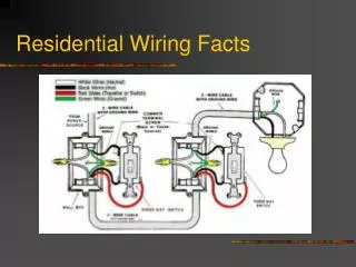
FACTS—UNIT #2 • By definitions, toggle switches and receptacles are devices because they carry current, but do not consume power • When a receptacle is connected to the branch-circuit wires, the outlet is called a “receptacle outlet.” • When a luminaire (light fixture) is attached to the branch-circuit wires, the outlet is called a ”lighting outlet.”
FACTS—UNIT #2 cont. • Dashed lines run from an outlet to a switch would normally indicate that the switch controls a portion of that outlet. The dashed lines are curved so that they cannot be mistaken for invisible edge lines. Outlets without curved dashed lines are independent outlets and have no switch control.
FACTS—Unit 2 cont. • Most modern surface-mounted luminaires (light fixtures) can be fastened to a luminaire (fixture) stud in the box or an outlet box or plaster ring using appropriate No. 8-32 metal screws. Special consideration has to be made for luminaires that weigh 50 lbs or more and for fixtures that weigh only 6lbs or less may be mounted with 6/32 screws on a standard outlet box (plastic or metal).
A box (or fitting) must be installed wherever there are splices, outlets, switches, or other junction points. The boxes must meet the following: • NEC 300.11 and 314.23: Boxes must be securely mounted and fastened in place. • NEC 300.15: Where conduit, electrical metallic tubing (EMT), nonmetallic-sheathed cable (Romex), Type AC cable or other cables are installed, a box or conduit body must be installed at each conductor splice connection point, outlet, switch point, junction point, or pull point.
Boxes cont.-- • NEC 300.15: Where cables enter or exit from a conduit or tubing that is used to provide cable support or protections against physical damage, a fitting shall be provided on the end(s) of the conduit or tubing to protect the cable from abrasion. • NEC 314.3: Permits nonmetallic outlet and device boxes to be installed where the wiring method is nonmetallic sheathed cable or nonmetallic raceway
Boxes cont.-- • NEC 314.3 (Exceptions) allows metal raceways and metal-jacketed cables (BX) to be used with non-metallic boxes provided all metal raceways or cables entering the box are bounded together to maintain the integrity of the grounding path to other equipment. • NEC 314.16: Boxes must be large enough for all of the enclosed conductors and wiring devices.
Boxes cont.— • NEC 314.16(C): The exception allows multiple cables to be run through a single knockout opening in a nonmetallic box (plastic), but not for metallic boxes. • NEC 314.20: Boxes installed in combustible material the box must be flush with the outer wall surface. If the boxes are installed in a noncombustible wall it is acceptable to have the front edge of the box set back not more than ¼ in. (6 mm) for the finished surface.
Boxes cont.-- • NEC 314.22: A surface extension from a box of a concealed wiring system is made by mounting and securing an extension ring over the concealed box or by a cover that secures the cover so that it will not fall off if it becomes loose. The grounding continuity must be independent of the connection between the box and cover. You may not use the mounting screws of the surface extension for the grounding or bonding of the extension ring, unless the mounting of the extension ring is independent from the cover.
Boxes cont. • NEC 314.23(B)(1): States that when a switch box or outlet box is mounted to a stud or ceiling joist with nails or screws through the box, the nails or screws must be not more than ¼ in. (6mm) from the back or ends of the box.—Nails or screws will not interfere with the wiring devices in the box.
Boxes cont.-- • NEC 314.25: In completed installations, all boxes shall have a cover, faceplate, or luminaire (fixture) canopy.—DO NOT LEAVE ANY ELECTRICAL BOXES UNCOVERED. • NEC 314.27(A): Boxes used at lighting outlets must be designed or installed so that a luminaire (lighting fixture) may be attached to it.
Boxes cont.-- • NEC 314.27(A) and (B): Listed outlet boxes are suitable for hanging luminaires (lighting fixtures) that weigh 50 lb. (23 kg) or less. Luminaires that weigh more than 50 lbs must be supported independently of the outlet box, or the outlet box must be “listed” for the weight to be supported.—Wall-mounted luminaires of less than 6 lb may be supported by a box or by a plaster ring secured to a box, by not less than two No. 6-32 or larger screws.
Boxes cont.-- • NEC 314.27(D): Standard outlet boxes must not be used as the sole support for ceiling suspended (paddle) fans unless they are specifically listed for this purpose. • NEC 314.29: Conduit bodies, junction, pull, and outlet boxes must be installed so the wiring contained in them is accessible without removing any part of the building.—NEVER INSTALL OUTLET BOXES WHERE THEY WILL BE INACCESSIBLE BEHIND OR ABOVE PERMANENT FINSHED WALLS OR CEILINGS.
Boxes cont. • NEC 314.71: Pull and junction boxes must provide adequate space and dimensions for the installation of conductors, and devices that are to be installed. • NEC 314.23 (B)(1)—stated that when a switch box or outlet box is mounted to a stud or ceiling joist with nails or screws through the box , the nails or screws must be not more than ¼ in. (6mm) from the back or ends of the box.—THIS ENSURES THAT WHEN NAILS OR SCREWS PASS THROUGH THE BOX, THEY WILL NOT INTERFERE WITH THE WIRING DEVICES IN THE BOX.
FACTS—UNIT 2 cont. • When two or more switches or receptacles are located at the same point , the switches or receptacles are referred to as being ganged, meaning that they are inside the same box. • If when installing an outlet box in a combustible wall and the box is not flush with the outer surface of the wall you may use a box extender, sometimes referred to as a “goof ring”.
FACTS—UNIT 2 cont. • When raised covers or plaster rings are marked with their volume in cubic inches, that volume may be added to the box volume to determine maximum number of conductors allowed in the combined box and raised cover
FACTS—UNIT 2 cont. • Switch boxes installed between studs using metal switch box supports, often referred to as “Kruse strips.” If wood strips are used, they must have a cross-sectional dimension of not less than 1 in. x 2 in. (25mm x 50mm)
FACTS—UNIT 2 cont. • Four-inch square boxes can be trimmed with one-gang or two-gang plaster rings where devices will be installed. Luminaires (lighting fixtures) will be installed , a plaster ring having a round opening should be installed.
FACTS—UNIT 2 cont. • Remodel work require the use of boxes having plaster ears and snap-in brackets that can be inserted from the front into the existing walls. Another popular method is to use boxes with plaster ears, inserting them from the front and then using “Madison Hold-Its” or “Madison Hangers”
Facts—Unit #2Spread of Fire: • Fire must be contained and not allowed to spread • Use of 5/8-in gypsum wallboard instead of the normal ½-in on the ceiling and on the walls between the garage and living areas and requiring “draft stopping” where ducts, cables and piping run through bottom (sole) and top plates.—This requires all holes or openings in these two plates to be calked using an approved fire rated calk or foam.
Facts—Unit #2Spread of Fire:—cont. • In walls, partitions, and ceilings that are fire-resistance-rated, are defeated if electrical boxes are installed “back-to-back” or in the same stud or joist space of common walls or ceilings. • Rating of fire-resistance materials are rated in hours.
Facts—Unit #2Spread of Fire:—cont.Fire rating of boxes— • “The surface area of individual metallic outlet or switch boxes shall not exceed 16 square inches” (i.e., a 4-in. square box is 4 in. x 4 in. = 16 in.2), • “the aggregate surface area of the boxes shall not exceed 100 in.2 per 100 ft.2 of wall surface,” • “boxes located on opposite sides of walls or partitions shall be separated by a minimum horizontal distance of 24 in. (600mm),”
Facts—Unit #2Spread of Fire:—cont.Fire rating of boxes— • ”the metallic outlet or switch boxes shall be securely fastened to the studs and the opening in the wallboard facing shall be cut so that the clearance between the box and the wallboard does not exceed 1/8 in. (3 mm).” • Using nonmetallic boxes in fire-resistance-rated walls, the restrictions are more stringent that for metallic boxes—i.e. non-metallic boxes may be restricted to openings not to exceed between 10 in.2 to 25 in.2.
Facts—Unit #2Spread of Fire:—cont.Fire rating of boxes— • Certain molded fiberglass outlet and device boxes are listed for use in fire-resistance-rated partitions without the use of putty pads, mineral wool batts, or fiberglass batts, provided a minimum horizontal distance of 3 in. (75 mm) is maintained between boxes and the boxes are not “back-to-back”.
Facts—Unit #2Spread of Fire:—cont.Fire rating of boxes— • Using and “intumescent” (expands when heated) fire resistant material that comes in pads, when properly installed may make the 24 in. separation between boxes not required. Providing that the outlet boxes must not be installed back-to-back.