Residential Wiring Facts
230 likes | 537 Vues
Residential Wiring Facts. Part 1 Power Generation and Transmission. 1.1) During electricity transmission the voltage is stepped up to as much as VAC so that current through the power grid is dropped extremely low to minimize energy loss.

Residential Wiring Facts
E N D
Presentation Transcript
Part 1 Power Generation and Transmission • 1.1) During electricity transmission the voltage is stepped up to as much as VAC so that current through the power grid is dropped extremely low to minimize energy loss. • 1.2) When power is needed in your neighborhood or, specifically, your home transformers are used to reduce the amount of voltage available for use from the 765,000 VAC used to transmit electricity through the power grid to 120 VAC you use in you day to day appliances and electrical devices. 765,000 step-down
1.3) Electrical energy, for large usages like cities and towns, can be created by many of the forms discussed earlier. Here in the Denver Metro area electricity generating turbines are powered by created by burning coal. steam
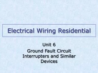
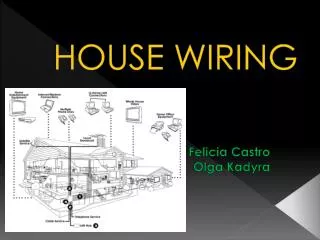
Part 2 Home Usage and Grounding 240 or 120 VAC. • 2.1) Appliances in your home use either • 2.2) All houses are equipped with a Rod, a metal rod driven into the earth, that is connected to the house’s electrical service panel to provide a pathway of conduction that will allow over load of current to be sent directly to the ground. This keeps your house safe from high voltages like lightening or power grid overloads. Grounding
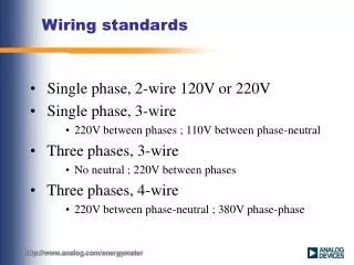
service • 2.3) The house panel (aka Circuit-Breaker Panel) is the main connection between the house and the power grid. • 2.4) The service panel is supplied with two 120 VAC lines and a single line from the setup down transformers on the power grid. • 2.5) In the case of a clothes dryer or water heater the two 120 VAC lines are connected in to create 240 VAC. neutral parallel
white • 2.6) In all case a neutral (usually ) wire which is used to complete the circuit and a green (or bare) wire which is used to connect the circuit to ground are supplied along with the “hot” single or double wire in the same wire run. • 2.7) Each and every single component of an electrical circuit must be to all the other parts to produce one cohesive system that will handle overload and short circuits. grounded
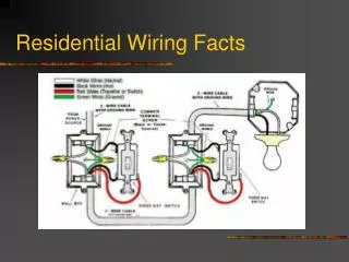
Part 3 Electrical Schematics and Wiring Diagrams schematic • 3.1) An electrical shows how electricity flows in a circuit, where as a wiring diagram show how electrical components are wired together. • 3.2) A wiring must show all circuit components and connections. diagram
symbols • 3.3) In a wiring diagram are used to represent circuit components. • 3.4) In a wiring diagram each component must show the of all wires and their color. termination
Part 4 Breakers and Circuit Run • 4.1) A circuit run is a circuit receiving power from the service panel that is protected by its own isolated • 4.3) A circuit breaker is a component that will automatically if the current load in the circuit run becomes higher than its rated value. • 4.2) Circuit breakers are usually valued at 15 or 20 amps and can protect approximately 8 to receptacles in a single circuit run. breaker disconnect 10
4.5) An End Run receptacle connection describes a receptacle that terminates the end of a circuit run and will only have wire feeding into the receptacle. • 4.6) A Middle Run receptacle connection describes a receptacle that has power running into it from a previous receptacle and then out from it to another receptacle down the line. Each middle run receptacle will have wire feeding in and out from it. • 4.7) A Circuit run is composed of a series of several connections of receptacles, switches and/or lights terminating at the last “End Run” receptacle.
4.8) A load first run circuit brings power into the outlet or light receptacle box then runs a two wire romex to the switch if necessary. • 4.9) A switch first run circuit brings power into the switch receptacle box and then daisy changes power to each consecutive receptacle box. • 4.10) A 3-way circuit is used to allow a circuit to be controlled by two different switches in different locations (i.e. a stairway).
part 5 Circuit components and connections • 5.1) Wire Connectors (aka wire nuts) are used to quickly connect multiple wires without soldering. • 5.2) Always make sure the wire insulation covers the wire all the way up into the wire nut (so no bare wire is showing).
5.2) Electrical tape should not be the actual connection devise but a backup to prevent possible short circuits. A wire nut, solder, or termination screws should always hold wire together not tape. • 5.3) Pigtails are short lengths of wire 4 or 5 inches long, used when two or more wire need to connect to a termination screw.
5.4) Red wire nuts should hold up to 4 or 5 wires (depends on gauge; 4) 12-gauge or 5) 14-gauge) • Yellow wire nuts hold up to 3 or 4 wires • Orange wire nuts hold up to 2 or 3 wires • color 12 guage14 guage • Red 2-4 wires3-5 wires • Yellow 2-3 wires2-4 wires • Orange 2 wires2-3 wires
5.5) Switches, outlets and other residential wiring components always have termination screws for the wire to connect to the component. Some newer components come with “push connectors” to make things go faster. • 5.6) A wire that connects to a component should be stripped back about 3/4 of an inch and a small loop is made that will connect to the termination screw in a clockwise direction. (clockwise so the wire will tighten with the screw).
5.7) Hot wire (usually black) is terminated to the brass screws and neutral wire (usually white) is terminated to the silver screws. • 5.8) Lineman’s pliers are used to twist together the wire ends to be connected by a wire nut. After the wire nut is secure use tape to enclose the connection to minimize to possibility of a short circuit or moister at the connection.
5.9) A 3-way switch is also known as a single pole double throw (SPDT) switch. • 5.10) A dimmer switch is also known as a potentiometer or a variable resistor.
Part 6 stripping wire • 6.1) Cut back the romex sheathing about 3 inches and snip off the hanging sheathing with a diagonal cutter or lineman’s pliers. • 6.2) Use a stripping tool to accurately cut off the individual wire insulation without cutting into the wire itself. • 6.3) Stripping tools often need to be adjusted for certain wire gauges. See information for each type of stripping tool before use.
part 7 Connecting Romex and Conduit to boxes • 7.1) Romex is the commercial title for sheathed wire (sets of wire wrapped together with an outer covering). • 7.1) No electrical connections should be made outside of and electrical box. • 7.2) Romex wire should be snuggly connected to the electrical box using a saddle clamp. • 7.3) The Romex feed wire should extend out at least 6 inches from the receptacle box to allow good connections to be made and for future rewiring.
7.4) Rigid or metal flexible conduit is snuggly connected to the electrical box using a knockout clamp or screw connector through a knockout then held tight by a locknut in the inside. • 7.5) Many newer plastic electrical boxes come with quick connect clamps that are directly manufactured into the electrical box. Push in the romex wire and it won’t come back out. • 7.6) When working with plastic electrical boxes always remember to ground the receptacle directly (a pigtail to the receptacle box is not necessary).
part 10 testing components • 10.1) Remember to always disconnect power before testing a circuit. • 10.2) If a connection is turned on and does not operation correctly a Multimeter set to continuity testing should be used to isolate the connection problem. • 10.3) Always check cables, romex and wire installation for cracks or splits before you uses them.
How is electrical energy created for large usages like cities and towns? • What does a switch look like in a wiring diagram?… or in a schematic? • Which symbol … • Which symbol shows wires being connected with a wire nut?