Cover
Cover. ASTRO ® XTS TM 5000 Model II Digital Portable Radio Interactive End-User Training. FIRE. Fleetmap. Fleetmap. 3. Fleetmap. The Fleetmap visually shows what channels/talkgroups are in the radio.

Cover
E N D
Presentation Transcript
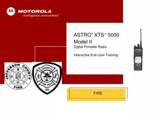
Cover ASTRO® XTSTM 5000 Model II Digital Portable Radio Interactive End-User Training FIRE
Fleetmap 3
Fleetmap • The Fleetmap visually shows what channels/talkgroups are in the radio. • The columns (A through F for personnel, A through G for command staff) represent the zones of the radio. • The softkeys on the radio change the zones. • The softkeys are labeled on the screen over which buttons control the zones. • The rows (1-16) represent the channel/talkgroup selector position within the selected zone. 4
Your Radio XTS 5000 Control Top Side Buttons 2-Position Concentric Switch 16-Position Select Knob Light Power On/Off Volume Control Keypad Lock Unprogrammed Push-To-Talk (PTT) Button 3-Position Toggle Switch Emergency/10-30
LED Status • RED • Solid • - PTT is pressed; radio is transmitting • Flashing • - Channel Busy • - Low Battery (lights while transmitting) • GREEN • Solid • - Self-test being performed RED LED GREEN LED
Battery • To remove the battery: • Turn the radio off. • Hold the radio with the back of the radio facing upward. • Push the battery release button on the bottom of the radio. • Lift the battery away from the radio and remove. • To install the battery: • Turn the radio off • Hold the radio with the back facing upward. • Align the three slots at the top of the battery with the three tabs on the back of the radio. • Push the battery down toward the radio until the battery clicks into place.
Belt Clip • To install the belt clip: • Remove the battery before installing or removing the belt clip. • Hold the battery with the back of the battery facing you. • Hold the belt clip with the top facing upward, and align the clip with the slots on the battery back. • Slide the belt clip downward into the slots until it clicks into place. • To remove the belt clip: • Pull away the metal tab at the top of the battery clip from the battery. • Slide the clip upward until it comes away from the radio. 1 2
Public SafetySpeaker/Microphone (PSSM) – 1 of 3 • To install the PSSM: • Turn the radio off. • Attach the accessory connector to the radio’s universal connector as follows: • a. Make sure the RF adapter has been installed in your radio before continuing with installation. • b. Looking at the antenna side of the radio, insert the bottom hooked end of the accessory connector into the slot below the universal connector. • c. While holding the accessory connector seated in the bottom slot, pivot the top of the accessory connector toward the radio until its RF interface connector aligns with the circular contact target on the RF adapter, then engage the accessory connector’s spring-loaded latch in the radio’s top slot. • Continued....
Public SafetySpeaker/Microphone (PSSM) – 2 of 3 • 3. Attach the correct (frequency-sensitive) antenna to the PSSM by screwing the antenna’s threaded end into the threaded antenna jack on top of the PSSM’s housing. • Rotate the antenna clockwise into the jack until it seats firmly. • 5. Secure the latch to the connector housing using the screw supplied. • The public safety speaker/microphone performs best • when it is operated with the antenna above the user’s • shoulder. • To transmit using the public safety speaker/microphone, • press the PSSM’s PTT and speak into the microphone’s • grille area. The red light-emitting diode (LED) on top of the • radio will light, indicating that the radio is in the transmit • mode. • The toggle switch next to the antenna lowers or increases the volume of the speaker. The speaker is loud when the switch is flipped towards the speaker, and quiet when the switch is flipped away from the speaker.
Public SafetySpeaker/Microphone (PSSM) – 3 of 3 • To remove the PSSM: • Turn the radio off. • Rotate the antenna counter-clockwise to unscrew it from the jack. • Remove the accessory connector by pivoting the top of the accessory connector away from the radio until it disengages from the RF adapter.
Radio On/Off/Volume To turn the radio on: Turn the On/Off/Volume Control knob clockwise. If the power-up test is successful, you briefly see SELF TEST, then the home display. If enabled, a power-up tone is also heard. If the power-up test is unsuccessful, you see ERROR XX/YY. (XX/YY is an alphanumeric code.) Click here to view further explanation of specific codes. To turn the radio off: Turn the On/Off/Volume Control knob counter-clockwise until it clicks. On/Off/Volume Knob SELF TEST
Zone Select(Menu) • To select a zone: • Press the Left side soft button labeled ZNUP to Zone up • Press the right side soft button labeled ZNDN • The zone name flashes on the display. • Press the CLCK button to change the time displayed on the radio. • Press and hold the Home button for 2 seconds to change the radio to Zone A POLICE 1. Zone Name a FIRE 5 OFD 8002 CLCK ZNUP ZNDN Push-to-Talk (PTT)
Channel/Mode Select(16-Position Select Knob) Channel/Mode Name To select a channel/mode: Turn the Channel/Mode Select knob to select the desired channel/mode. The new name will appear on the display. Click here to view an explanation of what happens if the trunked system’s central controller fails. Channel/Mode Select Knob a FIRE 5 OFD 8002 CLCK ZNUP ZNDN
Time-out Timer • The time-out timer turns off your radio’s transmitter. • The timer is set for 60 seconds. • Hold down the PTT button longer than the programmed time. • You will hear a low-pitched warning tone, the • transmission will cut off, and the LED will go out until you • release the PTT. • Release the PTT button. • The LED will re-light and the timer will reset. • Press the PTT button to re-transmit. The time-out timer restarts. • The timer will restart and the LED lights red. LED Push-to-Talk (PTT)
Transmit and Receive • To transmit: • Select the desired zone/channel. • Listen for ongoing conversations; if the channel becomes clear, proceed with your call. • Press and hold the PTT button to transmit and wait for the “Talk Permit” tone. The LED will light red. When speaking, keep the microphone 1-2" from your mouth. • Release the PTT button to receive (listen). • Click here for information on what happens if you go out • of range of the system. LED Push-to-Talk (PTT)
Scan On or Off(3-Position Toggle Switch) • The scan feature allows you to monitor traffic on • different channels by scanning a preprogrammed list • of channels. • To turn scan on: • Toggle the Scan switch to the predetermined position to enable scan. • The scan symbol ( ) will be displayed, indicating scan is • active. • A Scan Off • B Scan On • C Scan Program • To turn scan off: • Toggle the Scan switch “A” to disable scan. • The scan symbol ( ) will no longer be displayed, • indicating scan has been deactivated. c EVENT 3 ZNUP ZNDN Scan Switch
Scan List Edit(3-Position Toggle Switch and Menu) – 1 of 3 • This feature lets you change scan list members and • priorities. • To edit the scan list: • Toggle the Scan List Programming switch to the predetermined programming position. • You see the first available item and the view/program ( ) • symbol flashing, indicating the programming mode. You • will also see SEL, DEL, and RCL displayed as possible • selections. • Press the left or right side of the 4-way Navigation button to select the item to be changed. • Continued.... a FD TAC 80 Scan List Programming Switch
Scan List Edit(3-Position Toggle Switch and Menu) – 2 of 3 • Press the button directly below SEL or DEL or RCL. • SEL = add the currently displayed item to the scan list. • DEL = delete the currently displayed item from the scan list. • RCL = view the next available item. • OR • When adding a priority member press the button directly below SEL additional times. • You will see or or with a flashing dot. • = this item is in the scan list. • = this item is in the scan list as a priority-two • member. • (dot flashing) = this item is in the scan list as the priority-one member. • Note: You cannot delete a priority member. • Continued.... b MED 2 DEL SEL RCL
Scan List Edit(3-Position Toggle Switch and Menu) – 3 of 3 • Press the left or right side of the 4-way Navigation button to select more items to be added or deleted. • OR • Use the 16-Position Select knob to select additional items to be added or deleted. • Note: The maximum number of members for a trunking • priority monitor scan list is 15. • Toggle the Scan List Programming switch out of the programming position. 16-Position Select Knob a FIRE 6 Scan List Programming Switch
Emergency – SendEmergency Call(Top Button) • This type of dispatch gives your radio priority access • on a channel. The radio operates in the normal • dispatch manner while in emergency call: • Tactical/Non-Revert — You talk on the channel you selected before you entered the emergency state. • To send an emergency call: • With the radio turned on, press the Emergency button. • The current zone/channel is displayed alternately with • EMERGENCY, the LED lights red, and you hear a group • of short, medium-pitched tones. • If the selected channel does not support emergency, the • display shows NO EMERGENCY. Select a channel that • does show EMERGENCY. • Continued.... EMERGENCY CLCK ZNUP ZNDN LED Emergency Button
Emergency – SendEmergency Call(Top Button) • Note: To exit emergency at any time, press and hold • the Emergency button for about a second. • Press and hold the PTT button and announce your emergency into the microphone. • Release the PTT button to end the transmission and wait for a response from the dispatcher. • Press and hold the Emergency button for about a second to exit emergency. • While the Radio is in Emergency mode you will be unable to turn off the radio. To turn the radio off the Emergency must be cleared by pressing and holding the emergency button for 1-2 seconds. EMERGENCY CLCK ZNUP ZNDN Push-to-Talk (PTT) Push-to-Talk (PTT)
Display Light(Top Side Button) • If poor light conditions make the display or • channel numbers (around the 16-Position Select • knob) difficult to read: • Turn on the radio’s backlights by pressing the Light button. • These lights will remain on for a preprogrammed time • before they turn off automatically. • OR • You can turn them off immediately by pressing the Light • button again. Light Button
Keypad Lock(Side Button 1) If the keypad needs to be locked or unlocked you press this button once for each function. This is to prevent accidental bumping of the keypad and get the radio off the channel you are selected on. Keypad Lock Button
Clock (Time and Date)(Menu) – 1 of 2 • Using this special feature, you can program the time • and date as you might with other electronic devices. • The clock display is enabled by a qualified radio • technician. • To edit the time and date: • Press the right side of the 4-way Navigation button until CLCK is displayed. • Press the button directly below CLCK. • The current setting is displayed. • Press the button directly below EDIT. • The first item flashes. • Continued.... 10 : 46AM c EVENT 1 OFD 8002 CLCK ZNUP ZNDN
Clock (Time and Date)(Menu) – 2 of 2 • Press the up or down arrow of the 4-way Navigation button to change the selected item. • Note: Press the Home button at any time to return to the • home display without saving your changes. • OR • Press the right side of the 4-way Navigation button to move to an item you wish to change. • Press the up or down arrow of the 4-way Navigation button to change the selected item. • Press the right side of the 4-way Navigation button one or more times to move to an item in the date field. • Press the up or down arrow of the 4-way Navigation button to change the selected item. • When you have made all of your changes, press the button directly below SAVE to save your changes and return to the home display. • Note: If a call arrives while the radio is in the clock-setting • menu, the radio exits clock setting, your changes are lost, • and the call information is displayed. 24HR 17:03 MDY 10/14/09 SAVE
FAILSOFT • In the event of a system failure with the central controller for the trunking system, the radio will revert to “FAILSOFT” • In FAILSOFT, several of the channels/talkgroups go to the same frequency, and operate in a conventional manner. • Because of all of the channels combining, radio traffic should be kept at a minimum. 27