Project 1: Beakman’s Motor
420 likes | 608 Vues
Project 1: Beakman’s Motor. Part A: Background Part B: Building the Basic Motor Part C: Designing an Improved Motor Part D: Building and Testing an Improved Motor. Electromagnetic Revolution.

Project 1: Beakman’s Motor
E N D
Presentation Transcript
Project 1: Beakman’s Motor Part A: Background Part B: Building the Basic Motor Part C: Designing an Improved Motor Part D: Building and Testing an Improved Motor
Electromagnetic Revolution • These four equations epitomize the electromagnetic revolution. Richard Feynman claimed that "ten thousand years from now, there can be little doubt that the most significant event of the 19th century will be judged as Maxwell's discovery of the laws of electrodynamics" Electronic Instrumentation
Magnetic Attraction • It is possible to produce motion using magnetic attraction and/or repulsion • Either permanent magnets or electromagnets or both can be used Electronic Instrumentation
Magnetic Attraction and Repulsion • One of the many facts we all recall from our earliest science education Electronic Instrumentation
DC Motors • Opposite magnetic poles are shown in red and green. • As the motor rotates, the commutator causes the three electromagnets to turn on one at a time. • The magnetic attraction between the stationary magnet and the active electromagnet causes the motor to move. Electronic Instrumentation
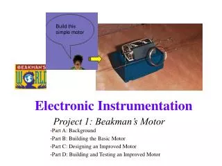
Beakman’s Motor • A simple DC motor with brushes made with a battery, two paperclips, a rubber band and about 1 meter of enameled wire. Electronic Instrumentation
Beakman’s World Movie Electronic Instrumentation
Materials • One D-Cell Battery (Supply your own – fresh batteries provide more power.) • One Wide Rubber Band • Two Large Paper Clips • One or Two Circular Ceramic Magnets • Magnet Wire (the kind with enamel insulation) • One Toilet Paper Tube (or paper tube) • Fine Sandpaper and wooden block for sanding surface Electronic Instrumentation
Measuring the Speed • As the coil rotates, it connects to the power supply about half the time. When this occurs, the voltage measured at the battery or power supply will drop (voltage divider action). Thus, a series of pulses will be observed, which can be used to determine the frequency of revolution. Zout Electronic Instrumentation
Battery Voltage Measuring the Speed • Voltage measured across the battery Electronic Instrumentation
Measuring the Speed • Good data should show consistent pulses. Note that the duty cycle is still not good in this case. • Poor data shows erratic contact is being made Electronic Instrumentation
Battery Resistance • Just like the function generator, batteries all have some kind of internal impedance. • By connecting the battery to a known resistor and measuring the resulting voltage, it is possible to determine the internal resistance. Electronic Instrumentation
Note http://hibp.ecse.rpi.edu/~connor/education/EIspecs/batteries.pdf Electronic Instrumentation
Task List • Build the basic motor • Demonstrate that it will run for at least 30 seconds • Take data that verifies the rpm of the motor • Take data on the components of the system • Improve the motor design, build and test it • Demonstrate that the motor works for at least 30 seconds without springs • Demonstrate that the motor works for at least 30 seconds with springs (hands and no hands). • Take data that verifies the rpm of the motor for all cases • Take data on the components of the new system Electronic Instrumentation
Building a Better Motor • Coil diameter. • Number of turns in coil. • Shape and stability of paper clip cradle (but no loops). • Gauge of wire • Shape of coil • Proximity to magnet • Coil balance • Coil weight • Springs to hold coil in cradle Electronic Instrumentation
Springs • Start by using a piece of wire to hold the coil into the cradle (hand-held springs). • Build mechanical springs to do the same type of thing without human intervention. • Springs cannot be part of the circuit. They cannot conduct electricity. • Examples of springs: Electronic Instrumentation
Project 1 Requirements • Motors must be built using a 1.5 volt battery or 1.5 Volts DC from the power supply. You must use the magnet wire and magnets available in the studio. • Supports must be made from paper clips • The cradle must have one open end. It cannot have any complete loops. • No more than 2 magnets & the magnets must be the ones supplied. • You can use a board and clay to support the cradle. • Springs must either be made of non-conducting material or not connected to source. Electronic Instrumentation
Project 1 Requirements • You cannot use your hands to hold the mechanical spring or hold the motor in the cradle. That is, you cannot touch the motor during its test. • You cannot use creative sanding to create a double duty cycle. • Your motor must run for 30 seconds. • Use the wooden blocks for sanding. Students caught sanding tables lose 1 point each time. • Clean up. Be careful not to drop long thin wires on the floor, they ruin the vacuum cleaners. Groups that leave their areas in a mess will lose 1 point each time. Electronic Instrumentation
Extra Credit Opportunities • Exceptionally creative approaches to implementation or in the final design • If your motor is one of the fastest in the section, you will be eligible for an additional point • Engineering problems are often solved by experimenting with different types of configurations, finding which changes have the most positive effects, and systematically choosing a course of action based on those experiments Electronic Instrumentation
Additional Topics of Interest • Magnetism • Early Compass • Levitation • Motors • DC Motors • Brushless DC Motors • Stepper Motors • MEMS • Battery Information • Beakman’s Motor Links Electronic Instrumentation
Magnetism • One of the first compasses, a fish shaped iron leaf was mentioned in the Wu Ching Tsung Yao written in 1040 Trinity College, Dublin Electronic Instrumentation
Animal Magnetism • A frog suspended in an intense magnetic field – all of us are paramagnetic • Much money is wasted on magnetic therapy Electronic Instrumentation
DC Motors • The stator is the stationary outside part of a motor. The rotor is the inner part which rotates. In the motor animations, red represents a magnet or winding with a north polarization, while green represents a magnet or winding with a south polarization. Opposite, red and green, polarities attract. Electronic Instrumentation
DC Motors • Just as the rotor reaches alignment, the brushes move across the commutator contacts and energize the next winding. In the animation the commutator contacts are brown and the brushes are dark grey. A yellow spark shows when the brushes switch to the next winding. Electronic Instrumentation
DC Motor Applications • Automobiles • Windshield Wipers • Door locks • Window lifts • Antenna retractor • Seat adjust • Mirror adjust • Anti-lock Braking System • Cordless hand drill • Electric lawnmower • Fans • Toys • Electric toothbrush • Servo Motor Electronic Instrumentation
Brushless DC Motors • A brushless dc motor has a rotor with permanent magnets and a stator with windings. It is essentially a dc motor turned inside out. The control electronics replace the function of the commutator and energize the proper winding. Electronic Instrumentation
Brushless DC Motor Applictions • Medical: centrifuges, orthoscopic surgical tools, respirators, dental surgical tools, and organ transport pump systems • Model airplanes, cars, boats, helicopters • Microscopes • Tape drives and winders • Artificial heart Electronic Instrumentation
Full Stepper Motor • This animation demonstrates the principle for a stepper motor using full step commutation. The rotor of a permanent magnet stepper motor consists of permanent magnets and the stator has two pairs of windings. Just as the rotor aligns with one of the stator poles, the second phase is energized. The two phases alternate on and off and also reverse polarity. There are four steps. One phase lags the other phase by one step. This is equivalent to one forth of an electrical cycle or 90°. Electronic Instrumentation
Half Stepper Motor • This animation shows the stepping pattern for a half-step stepper motor. The commutation sequence for a half-step stepper motor has eight steps instead of four. The main difference is that the second phase is turned on before the first phase is turned off. Thus, sometimes both phases are energized at the same time. During the half-steps the rotor is held in between the two full-step positions. A half-step motor has twice the resolution of a full step motor. It is very popular for this reason. Electronic Instrumentation
Stepper Motors • This stepper motor is very simplified. The rotor of a real stepper motor usually has many poles. The animation has only ten poles, however a real stepper motor might have a hundred. These are formed using a single magnet mounted inline with the rotor axis and two pole pieces with many teeth. The teeth are staggered to produce many poles. The stator poles of a real stepper motor also has many teeth. The teeth are arranged so that the two phases are still 90° out of phase. This stepper motor uses permanent magnets. Some stepper motors do not have magnets and instead use the basic principles of a switched reluctance motor. The stator is similar but the rotor is composed of a iron laminates. Electronic Instrumentation
More on Stepper Motors • Note how the phases are driven so that the rotor takes half steps Electronic Instrumentation
More on Stepper Motors • Animation shows how coils are energized for full steps Electronic Instrumentation
More on Stepper Motors • Full step sequence showing how binary numbers can control the motor • Half step sequence of binary control numbers Electronic Instrumentation
Stepper Motor Applications • Film Drive • Optical Scanner • Printers • ATM Machines • I. V. Pump • Blood Analyzer • FAX Machines • Thermostats Electronic Instrumentation
MEMS • Micro-Electro-Mechanical Systems (MEMS) is the integration of mechanical elements, sensors, actuators, and electronics on a common silicon substrate through the utilization of microfabrication technology. While the electronics are fabricated using integrated circuit (IC) process sequences (e.g., CMOS, Bipolar, or BICMOS processes), the micromechanical components are fabricated using compatible "micromachining" processes that selectively etch away parts of the silicon wafer or add new structural layers to form the mechanical and electromechanical devices. Electronic Instrumentation
MEMS Stepper Motor • This motor is very much like the other stepper motors mentioned above, except that it is 2D and very small Electronic Instrumentation
MEMS • Rotary motor • Steam Engine (single piston) Electronic Instrumentation
RPI MEMS Faculty • Prof. Yoav Peles http://www.rpi.edu/~pelesy/front_page.htm • Prof. Borca-Tasçiuc http://www.rpi.edu/dept/mane/deptweb/faculty/member/borca.html • CAT http://www.cat.rpi.edu/ • Prof. Kevin Craig http://www.rpi.edu/dept/mane/deptweb/faculty/member/craig.html Electronic Instrumentation
Battery Resistance Variation (AA Batteries) Electronic Instrumentation
Discharging Electronic Instrumentation
Additional Battery Information • http://www.buchmann.ca • http://www.batteryuniversity.com/index.htm • http://home.att.net/~mikemelni1/battery.html (source of data on previous slides) Electronic Instrumentation
Building Beakman’s Motor • The two most important sites • http://fly.hiwaay.net/~palmer/motor.html • http://www.scitoys.com/scitoys/scitoys/electro/electro.html#motor • Other Websites: • http://fly.hiwaay.net/~palmer/motor.html • http://www.scitoys.com/scitoys/scitoys/electro/electro.html#motor • http://www.micromo.com/library/docs/notes&tutorials/Developement%20of%20Electromotive%20Force.pdf • http://hibp.ecse.rpi.edu/~connor/motor_comments.html • http://hibp.ecse.rpi.edu/~connor/education/motorS98.html Electronic Instrumentation