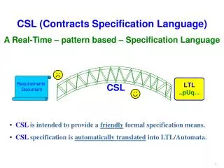
State-based Specification in System Behavior Analysis
Understand how state-based specification captures a system's condition using explicit descriptions and analysis tools. Learn about states, transitions, techniques, and methods like statecharts. Enhance system safety, design, and analysis with this approach.

State-based Specification in System Behavior Analysis
E N D
Presentation Transcript
State-based Specification Miheer Bhachech, Ebru Dincel, Nikunj Mehta
State-based Specification • Describe behavior of a system in terms of possible states and transitions • Capture the condition of a system in terms of its state • Hardware and control systems where the behavior of a system is reactive • State-based specification techniques have: • Explicit description and complete coverage of states and transitions • Specification language and formal reasoning • Precise mathematics • Analysis tools
Benefits • Objectives • Clarify requirements • Locate and correct inconsistency and non-determinism • Refine requirements consistently into design • Decomposition of system • Prove or disprove assertions about system behavior • End Result • Predictably safe systems, more deterministic behavior • Links between customer needs and system design
Concepts • State • A state represents the computational readiness of a system at that instance of time during its lifetime • Initial state • The state in which a system starts • Condition • Represents an existing on-going state of the system • Quantification • The application of a condition over more than one variable
Concepts (2) • Transition • A transition is a change in the state of the system • Event • An event is an instantaneous change in the environmental or internal condition of a system. • Action/activity • The function that is carried out or the event that is emitted upon the transition of the system from one state to another • Invariant • A global or local property that holds true for the duration of the system lifetime
Techniques and Methods • Finite state machines • Augmented transition networks • SDL • Petri nets • Sequence diagrams • Statecharts • Computational tree logic • ASLAN specifications • UML state diagrams
Statecharts • Purpose • Specification and design of discrete-event systems • Provide behavioral description of reactive systems When event α occurs in state A and condition C is true, transfer state to B • Features • State-transition diagrams • Hierarchy, concurrency and communication • Uses area and location of graphical objects • Statecharts = state diagrams + depth + orthogonality + broadcast-communication
Decomposition in Statecharts • Use of higraphs • Hierarchical graph • Super-states • Exclusive-OR combination of states • Economize number of arrows • Abstraction or refinement? • Capture a common property • Bottom up and top-down • Exclusive disjunction of individual states • Zooming
alarms-beep T hits T1 (P1) alarm1 beeps displays T hits T2 (P2) 30 sec in alarms-beep alarm2 beeps any button pressed both beep T hits T1 (P) alarms-beep T hits T1 (P1) displays T hits T2 (P2) 30 sec in alarms-beep any button pressed T hits T1 (P)
Default and History States • Default states • Equivalent to start states for FSM • History • (H) Record of the last state at the current level • (H*) Deep history stores last state at all levels current and below D D A A A alarm1 K H* H G H off A C d d D on B E
Orthogonality • AND combination of states • Concurrency and synchronization • Simultaneous transitions in component states • Independence • Independent transition in one of the component state • Orthogonality = concurrency + independence • Communication among states by common events • Exits • Synchronized, independent and e-transition exit
Y A D B G m b in (G) F a g d a C E
Semantics of statecharts • Challenges • Depth of states, non-determinism, concurrency • Use of communication mechanism for concurrency • One part generates and all other parts sense it • Atomic event propagation • State machine • State tree and a set of transitions • Nextstep(X, C, E) • Select relevant transitions by analyzing trigger for E • Check source configuration for ancestral relation of X • Analyze consequences of applying actions of transition • Generate next full basic configuration
Additional features • Condition and selection entrances • Abbreviated decisions • Parameterized states • Repeating structure across states, • Delays and timeouts • Prevent starvation and deadlocks • Overlapping states • Convert XOR into OR • Non-determinism • Assign probabilities to transitions
Integration With Other Methods • Pure statecharts represent control part only • Internal state change • Actions and activities • Generate events and change value of conditions • Activity charts for functional description • Module charts for structural description • Specify eventualities, absence of deadlocks, timing constraints using TL • Synthesis of statecharts from TL specs • Describe scenarios using TL and derive statecharts from a large set of scenarios
Merits and demerits • No explosive growth of states • Can be refined into designs • Simple but powerful notation and techniques • Tool support for editing and analysis - STATEMATE • Strong semantic underpinning • Rich graphical notation • Difficult to synthesize complex systems • Mapping between hierarchies of states and hierarchies of objects
Requirements Modeling • Applicable to verify • Safety properties of event-driven systems • Premise • Informal requirements specs • Implicit assumptions about the system • Formal Method • Requirement specs • An informal description of system behavior • Formalizing requirements • Adding the implicit assumptions in the specs • Dealing with non-determinism, ambiguity • Automated Model checking using logical formulas
SCR Concepts • Mode • Set of system states that share a common property • Modeclass • Set of modes, describing one aspect of the system’s behavior • Mode transition • Occurs between modes in the same modeclass due to system changes • Specified by conditions and events • Software requirements document • An informal specification of a system’s behavior • Safety properties • Global assertions, system invariants • System properties that must always hold
SCR Semantics • Events • @T(Cond1) – specifies the point in time when value of condition Cond1 changes from false to true • Cond1 is the events’ triggered condition • @T(Cond1) WHEN [Cond2] – event of Cond1 becoming true while condition Cond2 is also true • Cond2 is the events’ WHEN condition • Event Occurrence • Event @T(A) WHEN [B] • Three definitions of event occurrence • B is true throughout [t@T(A)-€, t@T(A)] • B is true throughout [t@T(A), t@T(A)+€] • B is true throughout [t@T(A)-€, t@T(A)+€] • We shall use the last definition since it distinguishes between WHEN conditions and triggered conditions
SCR Example TABLE 1: Mode Transitions For Temperature Control System • Each row specifies the event causing the transition from left mode to right mode • Some Global Constraints • OFF => ~Running • INACTIVE => (Running & TempOK) • HEAT => (Running & BelowDesiredTemp) • (Running&BelowDesiredTemp=>(HEAT | O(HEAT)))
Formalizing SCR Requirements • Implicit assumptions are added for automatic verification • Temperature cannot be Above, Below and OK simultaneously • Sequences of Instantaneous mode transitions • Example: HEAT-INACTIVE-OFF • Adding a new distinct mode transition (HEAT-OFF) • Desired level of determinism is achieved • Detecting instances of nondeterminism • Event (@F(Running)&@T(TempOk)) in HEAT triggers transitions into both OFF and INACTIVE • FORMALIZED MODE TRANSITIONS
Model Checking • Verification of safety properties • System is represented as a finite state machine • Transition conditions(input condition values) • Attributes • Safety properties-temporal formulas • Every atomic proposition is a CTL formula • If f & g are CTL formulas, so are ~f, f&g, f|g, AXf, EXf, A[ fUg ], E[ fUg ], AFf, EFf, AGf, EGF, AGf, EGF • We are interested in formulas of the form AGf since safety properties are invariant – for model verification • Examples • AG(OFF -> ~Running) • AG(INACTIVE -> (Running & TempOK))
Requirements to CTL Machines • CTL states • mode state - represents the system in the mode • exit state - represents the system leaving the mode • Marks readiness of the system to allow a state change ~Running & AboveDesiredTemp & RUNNING & AboveDesiredTemp & ~TempOk & ~BelowDesiredTemp ~TempOk & ~BelowDesiredTemp ~Running & TempOK & RUNNING & TempOK & ~BelowDesiredTemp & ~BelowDesiredTemp & ~AboveDesiredTemp ~AboveDesiredTemp RUNNING & BelowDesiredTemp & ~TempOK & ~AboveDesiredTemp ~Running & BelowDesiredTemp & ~TempOK & ~AboveDesiredTemp Fig. 2. CTL representation of multiple SCR events Off NoFailure Exit Off NoFailure Off NoFailure Exit Off NoFailure Exit
Invariant Properties • Mode invariants – • invariant properties of a system mode • true when system enters the mode, and is in the mode • Becomes true or false when system leaves the mode • EG: ~Running is an invariant property of mode OFF • State invariants - conditions that are always true when the CTL machine is in that state • Mode and state invariants must be equivalent • First Scenario: • State invariant is stronger than the mode invariant INV C ~C C ~C Fig. 3.State Invariant stronger than the mode invariant Fig.4. State Invariant equals the mode invariant Global Global Exit Global Global
Invariant Properties • Second Scenario: • Solution to the first problem results into a second scenario • State invariant is weaker than the mode invariant. E A & B ~A & B E ~E Fig. 5. State invariant is weaker than the mode invariant E A & B ~A & B & E E ~E Fig. 6. State invariant equals the mode invariant ModeX1 ModeY1 Exit ModeX2 ModeY1 ModeX1 ModeY1 ModeX1 ModeY1 Exit ModeX1 ModeY2 ModeX1 ModeY1 Exit ModeX2 ModeY1 ModeX1 ModeY1 ModeX1 ModeY1 Exit ModeX1 ModeY2
Merits & Demerits • The specification language is intuitive and scalable • Clarifies customer requirements • Reveals any ambiguity or nondeterminism • Provides deterministic requirement specifications • Analysis is automated • No Concurrency issues have been addressed • Single modeclass examples have been discussed • How are multiple modeclasses shown ? • How do they communicate ? • What happens to scalability ? • Adding more modeclasses increase number of modes, hence number of states resulting in complexity of states • Model checker is restricted to the study of FSM • System need not be an FSM • Requirement specs must be an FSM
A Specification LANguage • Purpose • Is specification correct with respect to critical requirements? • Generates lemmas (correctness conjecture) • Features • Hierarchical • Based on first order Predicate logic • Built on a FSM • Elements • state variables • Invariants • transitions
Notation • State variables change through transitions • X’= before X= after • e.g. A clock model Transition Tick Current_Time= Current_Time’ + 1
Mathematical Approach • System should always satisfy critical requirement • Basis of induction • Start with state invariant satisfying initial state • Initial condition • initial_assertion invariant_assertion • Inductive step • invariant_assertion’ & T invariant_assertion
ASLAN Example • Critical requirement : • the number of items in warehouse is never less than zero • Initial_assertion: • INITIAL Inventory >= 0 • Invariant_assertion: • INVARIANT Inventory >= 0 • Correctness conjecture: • Inventory >= 0 Inventory >= 0
Entry & Exit Assertions • Entry Assertion • Inventory > 0 • Exit Assertion • Inventory = Inventory’ - 1 • Inductive step: • invariant_assertion’ & entry_assertion’ & exit_assertion invariant_assertion Inventory’ >= 0 & Inventory’ > 0 & Inventory = Inventory’ – 1 Inventory >= 0
Top level specification SPECIFICATION Authentication LEVEL Top_Level TYPE Log_Entry IS STRUCTURE OF (Who:User, When:Time, Tried: Password, Result:BOOLEAN) CONSTANT Password_Ok(Password, Password): BOOLEAN VARIABLE Current_Time: Time, Login_Allowed, Sound_Alarm: BOOLEAN INVARIANT FORALL le: Log_Entry (le ISIN Log-- Password_Ok (User_Password(le[Who]), le[Tried]) = le[Result]) TRANSITION Login (u:User, p:Password) EXIT Log=Log’ UNION {le: Log_Entry (le[Who]=u & le [When]=Current_Time & le[Tried]=p & le[Result]=Password_Ok(User_Password(u),p))} & Current_Time>Current_Time’ IF Password_Ok(User_Password(u),p) THEN Login_Allowed & ~Sound_Alarm ELSE ~Login_Allowed & Sound_Alarm FI END Top_Level END Authentication
No Change States • Certain state variables are not mentioned in assertions • Assume no change in value • Exit value = Entry value 1) Variables whose new values were not referred in EXIT assertion 2)If new value of a state variable is mentioned in THEN(ELSE), but not in ELSE (THEN), assumed not to change in ELSE(THEN) 3)If new value of a state variable is referred in one half of ALT (procedural disjunction) not in the other, conjoin NOCHANGE to the half where it is not mentioned
Unparametrized Example User_Ok(p) & Login_Allowed ALT ~User_Ok(p) & Sound_Alarm User_Ok(p) & Login_Allowed & Sound_Alarm= Sound_Alarm’ ALT ~User_Ok(p) & Sound_Alarm & Login_Allowed= Login_Allowed’
Procedural vs. Nonprocedural • Easy vs. harder implementation • Problems with quantification: generated nochanges are universal, consistency problems • E.g. IF predicate1 THEN x(1)=1 ELSE x(2)=2 FI IF predicate1 THEN x(1)=1 & FORALL i: INTEGER (~(i=1| i=3 | i=4) - x(i)=x’(i)) ELSE x(2)=2 & FORALL i: INTEGER (~(i=2| i=3 | i=4) - x(i)=x’(i))
Merits and Demerits • Easier to grasp • Provides both logical and procedural constructs • Hierarchy supported • No conditional statement within quantification • Still need theorem prover for verification
Real-Time Systems and Object Paradigm • Real-Time System • A software system that maintains an ongoing and timely interaction with its environment. • Maintaining an ongoing interaction ? • System is constant, behavior comes and goes • Software – structure of interacting dynamic components • More importance is given on structure • Models have to be predictive, hence model not only structure & behavior, but also logical and physical resources and engineering infrastructure
Modeling Real-Time Behavior • Concurrent System • More than one flow of control • Multiple things take place at a time • UML Active objects • An object that owns a process or thread and can initiate control activity • Behavior modeling • Event-driven(reactive) behavior modeling • Time-driven behavior modeling
Event-driven behavior modeling • Functional behavior • Processing of services • Control behavior • Actions performed as a controlled entity within the overall system • Transition system formalism • Model of an entity that performs a transition from one state to another in reaction to the arrival of an event • Activity – event-response pairs • Concurrency and priority • Example: UML state machines • Resolves problem of conflicting control & functional behaviors in a RTS
UML State Machines • Example: ackB/ reset/ send/^A reset data/ data/ stop/ start/ error/ ackA/ send/^B Fig. 3. Functional Behavior: a communication protocol handler Fig. 4. A typical control behavior • Two different state machines describing different aspects of the same object • Have to be combined in some way ReadyToSendA Uninitialized SendingA SendingB Initialized Error ReadyToSendB Operational
Hierarchical states and transitions • Yields a nice separation of the two behaviors • Modification can be made independently • Using inheritance, the same control behavior can be used for modeling similar control behaviors reset/ reset/ data/ data/ stop/ start/ error/ Operational Uninitialized Error Initialized Ready ToSendA SemdomgA SendingB Ready ToSendB
Time-driven behavior modeling • Based on periodic activities • State machines can be used at the highest level of description of an object • Periodic behavior is activated by a periodic timeout event • When a timeout occurs, an internal transition associated with the operational state is triggered • The action associated with the transition is a periodic activity • Same object can perform multiple periodic activities at different rates, each of which handled by a separate transition triggered by it’s own timer.
Modeling Inter-object Behavior • Modeling behavior of a set of collaborating objects • Collaboration: society of classes, interfaces, and other elements that work together to provide some cooperative behavior • Different ways of modeling provided by UML • Sequence diagrams: show a set of objects & the messages sent and received by those objects, emphasizing on timing order of message • Interactions: a behavior comprising of a set of messages exchanged among a set of objects, to accomplish a purpose. • Activity diagrams: shows the flow from activity to activity within a system. Illustrates the dynamic view of the system • Protocols: a special type of UML collaboration that specifies the set of valid message exchange sequences • Defined independently of any specific objects or class • Reusable
Architectural Modeling • Formalizing architectural specifications • models can be analyzed for consistency and completeness • models are executable and allow early and precise assessment • implementations can be derived directly from architectural specifications using automatic code generation • Capsule • An active object that may have an internal structure described by a collaboration diagram • recursion allows modeling of complex structures • One or more ports handle all incoming & outgoing communications within a capsule • Makes the capsule a self-contained component, fully reusable
Rose RealTime • comprehensive visual development environment • powerful combination of notation, processes, and tools to meet real-time challenges • Automatic generation of complete C++ executables directly from system or component models • The Rose RealTime DOORS Link • Integration to DOORS requirements management tool & Rose RealTime modeling tool. • Provides the ability to link and trace requirements to software design elements and vice versa. • Ability to identify requirements not address in the design • Associates requirements to specific elements of the design
Merits & Demerits • UML is a standard for modeling system requirements and design • Easy to understand • Reusable stereotypes e.g Real Time clock • Provide a view of the system from an implementation aspect • Models are analyzable and executable • UML formalism is an issue • Ambiguous interpretations of a model • Model verification is doubtful