Download
1 / 14
140 likes | 142 Vues
service repair manual

E N D
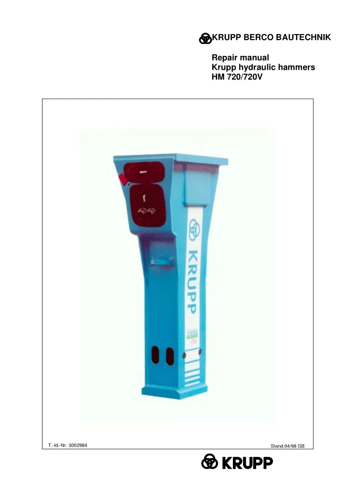
KRUPP BERCO BAUTECHNIK Repair manual Krupp hydraulic hammers HM 720/720V T.-Id.-Nr. 3002984 Stand:04/98 GB
Repair manaual HM 720/720V Repair manual Krupp hydraulic hammers HM 720/720V ©Krupp Berco Bautechnik GmbH Krupp Berco Bautechnik GmbH P.O.Box address: Postfach 10 21 52, D – 45021 Essen Postal address: Helenenstraße 149, D – 45143 Essen Telephone: +49 201 633 – 02 Fax: +49 201 633 – 1547 Fax for after-sales service: +49 201 633 – 1352
Repair manual HM 720/720V Contents Chapter Title Version Page 1. 1.1 General.........................................................................................04/98............... 1 Explanation of the symbols used in this repair manual.................................. 2 2. 2.1 2.2 2.3 2.4 Operational safety.......................................................................04/98............... 1 General................................................................................................................. 1 Accident prevention regulations............................................................................ 1 Tools, measuring and testing equipment.............................................................. 2 Operating media/consumables..............................................................................2 3. 3.1 3.2 3.3 3.3.1 3.3.2 3.3.3 3.3.4 3.3.5 Tools.............................................................................................04/98............... 1 General tools......................................................................................................... 1 Service Box 3........................................................................................................ 2 Special accessories...............................................................................................3 Accumulator filling device...................................................................................... 3 Power wrench........................................................................................................4 Heli Coil tools........................................................................................................ 4 Fitting aid for percussion piston.............................................................................5 Press-out aid for wear bushes...............................................................................5 4. 4.1 4.2 4.3 4.4 4.5 4.6 4.7 4.8 Dismantling the hydraulic hammer............................................04/98...............1 Removing the HM 720/V percussion mechanism from the hammer box.............. 1 Removing the high-pressure accumulator............................................................ 2 Removing the control slide valve...........................................................................3 Removing the frequency switching system........................................................... 3 Removing the cylinder cover................................................................................. 5 Removing the percussion piston........................................................................... 6 Removing the tie rods........................................................................................... 7 Removing the cylinder.......................................................................................... 7 5. 5.1 5.2 5.3 5.4 5.5 5.5.1 5.5.2 Checking the hammer box.........................................................04/98............... 1 Checking for cracks and indentations................................................................... 1 Wear to the bottom plate....................................................................................... 1 Checking the elastic pad....................................................................................... 2 Checking the damping elements........................................................................... 2 Checking the guide plates and the dust collar.......................................................3 Checking the guide plates..................................................................................... 3 Checking the dust collar........................................................................................ 4 Version 04/98 Contents 1
Repair manual HM 720/720V Contents Chapter Title Version Page 6. 6.1 6.2 6.3 6.4 6.5 6.6 6.7 6.8 6.9 6.10 Assembling the hydraulic hammer........................................................04/98...1 Tightening torques for screws and screw couplings on the HM 720/V..................1 Fitting the cylinder................................................................................................. 2 Fitting the percussion piston................................................................................. 2 Fitting the tie rods.................................................................................................. 3 Fitting the cylinder cover....................................................................................... 3 Fitting the frequency switching system..................................................................5 Fitting the control slide valve................................................................................. 6 Fitting the high pressure accumulator................................................................... 6 Fitting the piston accumulator............................................................................... 7 Fitting the HM 720/V percussin mechanism in the hammer box........................... 9 7. 7.1 7.2 7.3 7.4 7.5 Changing the seals.................................................................................04/98... 1 Changing the cylinder seals.................................................................................. 1 Changing the seals between cylinder and cylinder cover..................................... 3 Changing the seal on the control system.............................................................. 3 Changing the seals on the high pressure accumulator......................................... 3 Changing the seals on the sealing bush............................................................... 4 8. 8.1 8.2 8.3 8.4 8.5 8.6 8.7 8.8 8.9 8.10 8.11 8.12 8.13 8.14 8.15 8.16 8.17 Repair work..............................................................................................04/98... 1 Changing the screws on the high pressure accumulator...................................... 1 Changing the high pressure accumulator..............................................................1 Changing the tie rods............................................................................................ 2 Removing scores from control slide valve and bore..............................................2 Removing scores on percussion piston and cylinder bore.................................... 3 Replacing retainer bar and working tool................................................................3 Changing the wear bushes................................................................................... 4 Replacing the complete hammer box....................................................................6 Replacing guide plates and damping elements in hammer box............................6 Replacing the dust collar in the hammer box........................................................ 6 Repairing cracked welds....................................................................................... 7 Replacing the bottom plate on the hammer box....................................................7 Reworking the retainer pins for the damping elements......................................... 8 Weld seam preparation......................................................................................... 8 Preheating temperature........................................................................................ 8 Fillers.................................................................................................................... 8 Post-treatment of welds........................................................................................ 8 Authorised dealers and regional service centres Version 04/98 Contents 2
Repair manual HM 720/720V 1. General In order to maintain the operational safety and reliability of the HM 720/V hydraulic hammer, repair work should only be carried out by Krupp-trained specialists using genuine Krupp spare parts. Krupp-trained spe- cialists know which parts need replacing and when. Although this repair manual applies to the HM 720-1/V and HM 720-2/V hydraulic hammer models, the man- ual refers only to HM 720/V by way of simplification. Any specific differences between the two models are however highlighted. Version 04/98 Chapter 1 1
Repair manual HM 720/720V 1.1 Explanation of the symbols used in this repair manual To emphasise their importance, certain points in the repair manual are marked with symbols, which are de- scribed below: These passages contain information on the correct use of the hydraulic tool and are aimed at avoiding mistakes during operation. Please note! Passages marked in this way contain safety infor- mation and instructions aimed at avoiding dam- age. Warning! Passages marked in this way contain safety infor- mation and instructions aimed at preventing acci- dents and avoiding injury. Caution! Version 04/98 Chapter 1 2
Repair manual HM 720/720V 2. Operational safety Working tools should only be fitted in the way de- scribed in the operating manual. 2.1 General Caution! In order to maintain the operational safety and reli- ability of the hydraulic hammer, repair work should only be carried out by trained specialists using genuine Krupp spare parts. For this reason, repair work should only be entrusted to Krupp-trained specialists who know which spare parts need re- placing and when. The hydraulic hammer’s integrated piston accu- mulator is pressurised. Before dismantling the hydraulic hammer and be- fore removing filling valve "G", the piston accu- mulator must be fully depressurised. Never use nails, screwdrivers or similar objects to bleed off the gas since this would damage the fill- ing valve. The gas should only be bled off using the nozzle of the filling/test hose. Never use your fingers to check the alignment of the working tool recesses with the oblong holes for the locking bars. Never dismantle a hydraulic hammer which is still hot from running. Risk of burns! Wait until the hy- draulic hammer has cooled down before disman- tling it. Collect any oil which runs out and dispose of it correctly. 2.2 Accident prevention regula- tions Caution! To avoid the risk of injury, please observe the following instructions. Before starting work: Familiarise yourself with the repair manual and the appropriate regulations before starting work on the hydraulic hammer. When using or working on hydraulic hammers in the countries of the European Union, the regula- tions contained in the EC machinery directive 89/392/EEC must be observed and followed, as must national regulations governing pressurised vessels. In countries outside the European Union, the valid local statutes and regulations shall apply. The hydraulic hammer should only be repaired by specialists. When lifting/transporting the hydraulic hammer, use only the lug provided and hoisting equipment with sufficient capacity. Clear hand signals must be agreed on with the hoist operator beforehand. Never stand beneath hoisted loads. Stand the hydraulic hammer in a suitable device and secure it against falling over. The repair area must be clear and easily accessi- ble. Always wear protective glasses when fitting or re- moving the working tool as metal splinters may fly off when hammering out the locking pins. Caution! Risk of explosion! The piston accumulator must only be filled with ni- trogen from the green cylinder. Make sure that no other gas (e.g. air or oxygen) is allowed into the piston accumulator. When attaching the adapter use only Allen screws with a material quality of ?s = 640 N/mm² (material quality 8.8). Version 04/98 Chapter 2 1
Repair manual HM 720/720V 2.3 Tools, testing equipment measuring and The tools required for dismantling and re-assem- bling the HM 720/V are to be provided by the user (see Chapter 3.1). The special accessories used in this section are listed in Chapter 3.3. 2.4 Operating consumables media/ Use Running HM 720/V Comments In warmer cli- mates, oils with a higher viscos- ity class should be used Krupp paste (see oper- ating manual) HD oil HLP 32 the chisel High-perform- ance grease solids content Lubricating the working tool bearing with Nitrogen N2 Filling the - high pressure accumulator - piston accumulator Removing scores Caution! Abrasive ishing grain 600 pol- paper, Version 04/98 Chapter 2 2
Repair manual HM 720/720V 3. Tools 3.1 General tools The tools are required for repair work are listed below: Designation Part.-ident.-no. Qty. Sledgehammer Grease gun Slugging ring spanner Heavy-duty box spanner Jaw spanner Jaw spanner Jaw spanner Jaw spanner Jaw spanner Jaw spanner Socket key Socket key Socket key Socket key Socket key Claw spanner Claw spanner Allen key Allen key Allen key Allen key Power screwdriver insert Screwdriver Torque wrench 4 kg Compl. Size 55 Size 55 Size 46/50 Size 41/46 Size 30/32 Size 19/24 Size 13/15 Size 10/13 Size 30 Size 24/27 Size 22 Size 14 Size 8/9 Size 46 Size 50 Size 22 Size 17 Size 14 Size 5 Size 55 / 1 ½“ 8 mm 140-760 Nm / ¾“ 1146433 3034567 0439439 0478217 0437943 0430613 0119581 0430652 0119582 1031834 1146183 0431002 1031835 3031396 0430991 0314519 0478861 0209445 0209252 0204963 0209249 1 1 1 1 1 1 1 1 1 1 1 1 1 1 1 1 1 1 1 1 1 1 1 1 0328143 Version 04/98 Chapter 3 1
Repair manual HM 720/720V 3.2 Service Box 3 The tools required for service work on the ham- mers are contained in Service Box 3. Fig. 1 Service Box 3 Dimensions Length 760 mm Width 215 mm Height 250 mm Service Box 3 and contents can be or- dered under part ident. no. 3034016 Part. Item. Qty. Designation ident. no. - 1 Toolbox, empty 2267014 1 1 Chisel paste 1850852 2 1 Nitrogen cylinder 2l 1846262 3 1 Filler valve 1329516 4 1 Test pressure gauge 1329518 5 1 Hose 1329517 6 1 Test gauge HM 720/V 1852167 7 1 Test gauge HM 960/V 1852169 Pin punch d=15,5 L=130 Claw spanner size 50 tommy bar 8 1 1848819 9 1 0478861 10 1 Screwdriver 5 0209249 Hexagonal head bolt M 12x150 11 1 0103866 Fig. 2 Service tools Version 04/98 Chapter 3 2
Repair manual HM 720/720V 3.3 Special accessories This chapter lists the special tools and apparatus which can be purchased separately from Krupp Berco Bautechnik to equip the workshop. 3.3.1 Accumulator filling device 4 The tools listed in the table below are used to fill the high-pressure accumulator. The nitrogen cyl- inder (2/2) and the filler valve (2/3) from Service Box 3 are also required for filling. 1 2 3 Part ident. no. 0920415 Item Designation 1 Filling device with pressure gauge, check valve, Phillips screwdriver and tommy screw, as well as items 2-4 Mushroom head adapter Phillips screw insert Filling hosw 2 3 4 1329889 1329890 1329805 Fig. 3 Accumulator filling device Version 04/98 Chapter 3 3
Thank you very much for your reading. Please Click Here. Then Get COMPLETE MANUAL. NO WAITING NOTE: If there is no response to click on the link above, please download the PDF document first and then click on it.
Repair manual HM 720/720V 3.3.2 Power wrench You can choose between an electronic or a hy- draulic power wrench. Fig. 4 Electronic power wrench 3.3.3 Heli-Coil tools The tools listed in the table below are used to re- place the Heli-Coil inserts Part Item Designation Use ident. no. Fig. 5 Hydraulic power wrench Screw tap M 16 Threaded insert M 16 Screw-in tool M 16 Cylinder cover trol system, high sure mulator) 1 0920361 (con- 2 1031915 pres- accu- 3 0920354 Fig. 6 Heli-Coil tool Version 04/98 Chapter 3 4
Repair manual HM 720/720V 3.3.4 Fitting piston aid for percussion Designation Part ident. no. Eye bolt 1331717 Fig. 7 Fitting aid 2 1 3.3.5 Press-out aid for wear bushes Item Designation Part ident. no. 1333443 0332324 0332323 0981669 0981667 - 1 2 3 4 Press-out tool, compl. Grip Screw Press-out element Press-out element 4 3 Fig. 8 Press-out aid Version 04/98 Chapter 3 5