Download
1 / 33
330 likes | 512 Vues
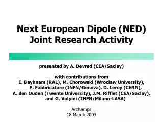
Next European Dipole (NED) Status Report. Arnaud Devred CEA/DSM/DAPNIA/SACM & CERN/AT/MAS on behalf of the NED Collaboration HHH General Meeting CERN 11 November 2004. NED Phase I. The Phase I of NED is articulated around four Work Packages and a Working Group

E N D
Next European Dipole (NED) Status Report Arnaud Devred CEA/DSM/DAPNIA/SACM & CERN/AT/MAS on behalf of the NED Collaboration HHH General Meeting CERN 11 November 2004
NED Phase I • The Phase I of NED is articulated around four Work Packages and a Working Group • 1 Management & Communication (M&C), • 2 Thermal Studies and Quench Protection (TSQP), • 3 Conductor Development (CD), • 4 Insulation Development and Implementation (IDI), • 5 Magnet Design and Optimization (MDO) Working Group.
TSQP Work Package • The TSQ Work Package includes two main Tasks • development and operation of a test facility to measureheat transfer to helium through conductor insulation • (CEA and WUT; Task Leader: B. Baudouy, CEA), • quench protection computation • (INFN-Mi; Task Leader: G. Volpini).
GHe LHe Pumping Cryogenic vessel Heat exchanger piping Insert Heat exchanger Expansion valve He I Radiation shields He IIp Experimental volume He IIs Vacuum container Heat-Transfer Measurement Task (1/2) • CEA has designed a newpressurized, He-II, double-bath cryostat. • The cryostat is being manufactured under WUT supervision and is scheduled for delivery to Saclay in the first quarter of 2005. Schematic of double-bath cryostat for heat-transfer measurements (courtesy F. Michel, B. Baudouy and B. Hervieu, CEA)
Heat-Transfer Measurement Task (2/2) • Measurements will be performed for various insulation systems and on two types of samples: 1-D drum samples, to study basic phenomenon and stack samples representative of actual magnet coils. Drum Sample (courtesy B. Baudouy, CEA) Stack Sample (courtesy N. Kimura, KEK)
Magnet Cooling • In complement to the heat-transfer measurement Task • D. Richter (CERN) will analyze available LHC magnet test data at high ramp rate to determine how well these measurements on actual magnets correlate with the Saclay measurements for a similar insulation system, • R. van Weelderen (CERN) has undertaken a review of magnet cooling modes to estimate, on the cryogenics system point of view, the limitations on power extraction and provide guidance on how to improve cooling of magnet coils.
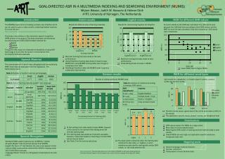
Quench Protection Task (1/2) • INFN-Mi has completed a survey of thermal properties and has studied how the error bars on the data may influence the results. Comparison of MIITs computations for impregnated NED cables relying on different data sources (courtesy M. Sorbi, INFN-Mi)
Quench Protection Task (2/2) • INFN-Mi is now undertaking systematic quench protection studies, starting from the 88-mm-aperture, cosq, layer design chosen as reference for NED. Hot-spot temperature computations using the QLASA code for the NED, 88-mm-aperture, cosq, layer baseline design (courtesy M. Sorbi, INFN-Mi)
TSQP Planning • Collaboration between CEA and WUT is off to a good start –enthusiasm of team compensates lack of human resources. • All tasks are on time!
CD Work Package • The CD Work Package includes four main Tasks • preliminary magnet design aimed at deriving meaningful conductor specifications (CERN; Task Leader: D. Leroy), • wire and cable development through two industrial sub-contracts, investigating two different manufacturing processes: Enhanced Internal Tin and Powder in Tube, • (under CERN supervision; Task Leader: D. Leroy), • wire and cable characterization • (CEA, INFN-Ge, INFN-Mi, and TEU; Task Leader: A. den Ouden, TEU), • mechanical FE analysis of cabling effects • (INFN-Ge; Task Leader: S. Farinon).
Preliminary Design Task (1/3) • To derive meaningful conductor specifications, CERN has investigated two types of cosq, dipole magnet designs: a layer-type and a slot-type. • The investigation was carried out for three apertures: 88 mm, 130 mm and 160 mm and aimed at a 13-to-15-T bore field. 88-mm-aperture, layer type 88-mm-aperture, slot type (courtesy D. Leroy and O. Vincent-Viry)
Preliminary Design Task (2/3) • The preliminary design study led to the definition of strand and cable parameters suitable to NED. • The study shows that, at 4.2 K, the bore field stays around 14 T with a quench field of ~15 T on the conductor. • Hence, to reach bore fields higher than 15 T the magnet should be operated at 1.9 K. • NB: the He-II operation may also be required to improve cooling under high beam losses.
Preliminary Design Task (3/3) • The preliminary design study also shows that, for the two-layer design at 14 T, the Lorentz stress accumulation in the azimuthal direction reaches ~150 MPa for the 88 mm aperture and is in excess of 200 MPa for the 130 and 160 mm apertures. • A reduction in azimuthal stress accumulation can be obtained by decreasing the overall current density in the coils while increasing the coil thickness, which leads to a three- or four-layer design. • An alternative for larger apertures is to change of magnetic configuration altogether as in the case of the slot-type design. • To be conservative, the 88-mm-aperture, cosq, layer design has been chosen as reference design.
NED Strand Characteristics • The main NED strand characteristics are • diameter 1.250 mm, • effective filament diameter < 50 mm, • Cu-to-non-Cu ratio 1.25 ± 0.10, • filament twist pitch 30 mm, • non-Cu JC1500 A/mm2 at 4.2 K and 15 T, • minimum critical current 1636 A at 12 T, • 818 A at 15 T, • N-value > 30 at 4.2 K and 15 T, • RRR (after heat treatment) > 200. • It is also requested that the billet weight be higher than 50 kg.
NED Cable Characteristics • Although the final cable dimensions will only be decided later on, the main cable parameters used in the reference, 88-mm-aperture, cosq layer design are • width 26 mm, • mid-thickness 2.275 mm at 50 MPa, • keystone angle 0.22 degrees, • number of strands 40, • minimum critical current 58880 A at 4.2 K and 12 T, • (with field normal to broad face)29440 A at 4.2 K and 15 T, • RRR (after heat treatment) > 120, • minimal cable unit length > 145 m. • The cable critical currents assume a cabling degradation of 10%.
Conductor Development Task • Following a market survey and a call for tender under CERN rules, two contracts for the production of a few hundred meters of cables have been awarded late September to • Alstom/MSA, France (Enhanced-Internal-Tin process), • SMI, the Netherlands (Powder-In-Tube process), with EAS, Germany as subcontractor. • The contracts will be monitored by CERN and extend over a 2-year period. • Discussions are are ongoing with OAS, Finland, who may join the program without receiving EU-funding.
Conductor Characterization Task (1/3) • Representatives of interested parties (CEA, CERN, INFN-Ge, INFN-Mi and TEU) have set up a Working Group on Conductor Characterization (WGCC), Chaired by A. den Ouden, TEU. • The WGCC is charged with the definition and development of standardized procedures to measure the critical current, magnetization and RRR of virgin, deformed and extracted strandsand has the responsibility for certification of the measured data. • Following the example of the VAMAS program, the WGCC has initiated a cross-calibration program of critical current test facilities, whose conclusions are due in June 2005.
Conductor Characterization Task (2/3) • Magnetization measurements will be performed under the supervision of INFN-Ge using a SQUID magnetometer and a Vibrating Sample Magnetometer (VSM). • The measurements will be performed as a function of field to appreciate the effective filament diameter and the presence or not of flux jumps. Exploratory measurements on a 5-mm-long Nb3Sn wire sample (SQUID measurements are courtesy of C. Ferdeghini, INFM/Genova; VSM measurements are courtesy of U. Gambardella, INFN/Frascati)
FNb=65 mm Conductor Characterization Task (3/3) • The magnetization measurements will also be performed as a function of temperature to study various issues, such as the proportion of un-reacted Nb in PIT wires. (courtesy M. Greco, INFN/Genova) (courtesy C. Ferdeghini, INFM/Genova)
Mechanical FE Analysis Task • INFN-Ge is developing a mechanical FE model to simulate the effects of cabling on un-reacted, Nb-Sn wires and optimize their design. Examples of mechanical FE model for an old “internal-tin” wire design and of Von Mises strain due to a diameter reduction of about 40% (courtesy S. Farinon, INFN-Ge)
CD Planning • Start date of 3.4 delayed by 3 months due to longer contract negotiations than anticipated. • End date of 3.4 delayed accordingly. • End date of 3.5 delayed to match that of 3.4. • End dates of 3.6 and 3.5 not moved due to some built-in slack in initial program.
IDI Work Package • The IDI Work Package includes three main Tasks • redaction of an engineering specification and definition of characterization tests, • (CCLRC and CEA ; Task Leader: E. Baynham), • studies on “conventional” insulation systems relying on ceramic or glass fiber tape and vacuum-impregnation by epoxy resin • (CCLRC; Task Leader: E. Baynham), • studies on “innovative” insulation systems relying on pre-impregnated fiber tapes and eliminating the need for a vacuum impregnation • (CEA; Task Leader: F. Rondeaux).
Insulation Specification • A basic engineering specification for the conductor insulation of a 15-T dipole magnet has been developed under CCLRC supervision. • The main parameters are • thickness 0.2 mm per conductor face, • dielectric strength 1 kV inter-turn in He at 300 K, • compressive strength > 200 MPa at 300 K and 4 K, • short-beam shear strength > 50 MPa at 4 K, • transverse tensile strength > 25 MPa at 4 K, • thermal contraction 0.3-0.4% between 300 & 4 K, • thermal conductivity > 20 mW/K at 4 K, • thermal cycle > 10, • running cycle > 100.
Precrack (release film) Crack growth from test Conventional Insulation Development • The CCLRC program on conventional insulation will address • glass fiber sizing issues, • radiation-hard resin alternatives, such as cyanate esters, • improved filler materials, such as nanoclays or dendritic powders. • CCLRC is also looking into fracture testing Example of Double Cantilever Beam(DCB) test sample (courtesy S. Canfer, CCLRC)
Innovative Insulation Development • CEA will pursue its ongoing development on innovative insulation • designed to enable • 1) ”controlled” pre-impregnation(in particular in terms of thickness) of glass or ceramic fiber tape, 2) wrapping of un-reacted conductor and winding of insulated conductor on small radii of curvature, 3) phase transformation of pre-impregnation during coil heat treatmentso as to confer a rigid shape to the coil and eliminate the need of a subsequent vacuum impregnation of epoxy resin. • The Task will concentrate more specifically on • optimization of nature and weaving of the fiber tape, • characterization and improvement of mechanical properties after heat treatment.
IDI Planning • Scope of 4.3.5 has been modified to include radiation tests and the end date has been moved to 30 June 2006. • Start date of 4.4 delayed until 1 January 2005 due to lack of human resources at CEA (permanent staff contribution). • End date of 4.4 delayed accordingly.
MDO Working Group (1/3) • The MDOWorking Group is made up of representatives from CCLRC, CEA, CERN and CSIC/CIEMAT • (Chairman: P. Védrine, CEA, Technical Secretary: F. Toral, CIEMAT). • Its main charge is to address the following questions • How far can we push the conventional, cosq, layer design in the aperture-central-field parameter space (especially when relying on strain-sensitive conductors)? • What are the most efficient alternatives, in terms of performance, manufacturability and cost?
MDO Working Group (2/3) • The MDO WG has selected • a number of magnetic configurations to be studied, • ranges of design parameters, • terms of comparison between solutions. • Each Institute participating to the WG will completely study one or two configurations. • Results of the comparative study are expected by December 2005. • Preliminary results of this study have been shared with the Fusion community (“EFDA” Dipole).
MDO Working Group (3/3) • Examples of alternativedipole magnet configurations to be optimized and compared Window-frame design proposed by CEA (courtesy H. Felice and P. Védrine) Motor-type design proposed by CIEMAT (courtesy S. Sanz and F. Toral)
Conclusion • All the tasks of the CARE/NED JRA have been launched and are well under way. • In particular, the industrial subcontracts for conductor development have been signed at the end of September 2004, thanks to D. Leroy diligence. • The program is initiating the desired synergies among the various European partners involved.
Perspectives • There is a reasonable hope of finding the funding necessary to carry out Phase II (model magnet manufacturing and test) at the 2008 horizon. • A possible scenario under consideration is a CSIC/CIEMAT-CEA-CERN collaboration where • CSIC/CIEMAT would manufacture the coils, • CEA would integrate the cold mass, • CERN would upgrade the FRESCA systems and cold test the model magnet.