Download
1 / 1
10 likes | 135 Vues
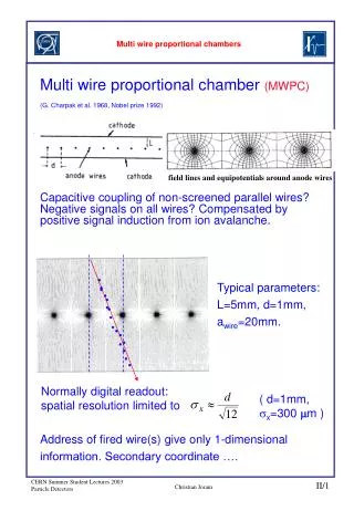
Calorimeters. Cross section of a 4-gap MWPC. Muon Detectors. RICH-2. Tracker. Iron Filters. Magnet. RICH-1. Vertex Locator. Anode Wires. Cathode Pads. 5 Muon Stations. HV bar. side bar. side bar. camera shot of 3 wires. wire distance measurement. read out bar. TEST:. panel.

E N D
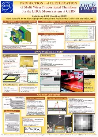
Calorimeters Cross section of a 4-gap MWPC Muon Detectors RICH-2 Tracker Iron Filters Magnet RICH-1 Vertex Locator Anode Wires Cathode Pads 5 Muon Stations HV bar side bar side bar camera shot of 3 wires wire distance measurement read out bar • TEST: panel wire pitch: measured by 2 cameras with telecentric lenses wire tension: measurement of wire oscillation, excited by high voltage pulses MWPC Sandwich Principle [mbar] relative gas gain [G0] pad number in y Test setup pad nr in x Relative Gas Gain distribution over one gas gap PRODUCTION and CERTIFICATION of Multi Wires Proportional Chambers for the LHCb Muon System at CERN K.Mair for the LHCb Muon Group CERN* Poster anlässlich der 55. Jahrestagung der Österreichischen Physikalischen Gesellschaft, September 2005 The Large Hadron Collider beauty experiment Multi Wire Proportional Chambers (MWPC) in the LHCb Muon System for precise measurements of CP violation and rare decays: for fast muon triggering and offline muon identification • A muon trigger is given by a • coincidence of all 5 muon stations within 25ns • >99% efficiency/station in 20ns time window • Time resolution <3ns • Up to 500 kHz/cm2 • total of 1368 MWPC in the Muon System Design Parameters: • Wire: Gold-plated Tungsten, 30 μm Ø • Wire spacing: 2 mm • Wire length: 250 to 310 mm • Wire mechanical tension: 65 gr • Gas gap: 5 mm • Gas mixture: Ar/CO2/CF4 (40:55:5) • Operation Voltage: HV = 2.650 kV • Field on wires: 262 kV/cm • Field on cathodes 6.2 kV/cm • Gas gain: G ≈ 50 000 • Gain uniformity: ≤ 30% • Rate/channel: < 1 MHz • Segmentation: • Catode Pads on PCB with gold-coated copper foil • Gold plated tungsten anode wires grouped in strips • 4-gap MWPC-Sandwich: • 2 double-side wired panels in between • 3 non-wired cathode panels The aim of the LHCb experiment is to fully investigate CP violation in the Bd and Bs systems, and to possibly reveal new physics beyond the Standard model. MWPC Production at CERN Panel Production Panel Wiring Automatic Wiring Machine • Cathode Panel: • Printed Circuit Board (PCB) • coated by 35 μm copper • 5 μm nickel, 0.2 μm gold • Procedure: • panel fixed between 2 bolts along HV and read-out bar to guide wire • 1 bolt ring-like, 1 bolt double spiral • bolt pitch 2mm • panel in wiring automate • first wire aligned by hand, then automatic spooling • wires glued and soldered to panel • Non-wired Panels: • Gas inlets • Connectors for pad read out • Kapton foil Cathode Panel • Wiring Tolerances: • nominal wire distance: 2 mm • 95% of all distances within 50 μm • all within 100 μm • nominal wire tension: 65 gr • all values above 50 gr • TEST: half gap size • Wired Panels: • 2 wire fixation bars (HV, read-out), 2 side-bars • bar thickness defines half-gap size: 2.5 mm • Precise bars gluing wire pitch and tension measuring device wire sample • Specification: • half-gap size: • 2.5 mm • tolerance: • 50 μm Panel Finalization Chamber Assembly • sandwich: 3 non-wired, 2 wired panels • gap size defined by 2.5 mm bars + • 2.5 mm spacers between layers • gas tight by O-rings • wires cutting • components soldering • final inspection (microscope) • HV training Chamber Certification Chamber Conditioning Gas Gain Uniformity Test • Specification: • Nominal Gas Gain: G0 = 50 000 • uniformity within one gas gap: 95% of gap area must • provide a gas gain within 30% G0 • uniformity between different gas gaps: average gap gas • gain variation within 25% G0 • Principle: • 241Am source emits 60 keV gamma rays • excitation of copper in panel → 8 keV gamma rays • (absorption length less than 1 mm) • photoelectric effect in Ar (gas) → electrons of few keV • collected signal on anode → ADC counts distribution with • peak position proportional to gas gain • Wire Conditioning: • apply negative HV up to -2300V • tip-like dirt on wires → e--emission • electromagnetic wire cleaning • test: apply positive HV up to +2900V • check currents with radioactive source • Cathode Conditioning: • apply positive HV, turn gamma-ray on • observe Malter currents due to • deposits on cathode (~15% of all gaps) • “heal” with gamma–ray exposure (GIF) • and CF4 (~ 100 hours exposure time) • no dark current → conditioning finished Gas Leak Test • Specifications: • < 2 mbar leak / hour at 5 mbar overpressure • Measurement principle: • Test against a gas-tight-proved reference • chamber • measure overpressure for 4 hours • measure internal parameters: T, P • TCh = TRef = const. • dV/V ~ d(DPCh-DPRef)/PCh • absolute error on Patm cancels out * J.-S. Graulich (Université de Genève), A. Kachtchouk (Petersburg Nuclear Physics Institute), K.Mair (CERN), B. Schmidt (CERN), T. Schneider (CERN)