Analyzing Operational Issues with BPMs and BPIs: Non-linearity, Delay, and Signal Processing
This document discusses the operational challenges faced with Beam Position Monitors (BPMs) and Beam Current Indicators (BPIs), particularly focusing on known inconsistencies and non-linear responses in BPIs. Analysis from diagnostic data of December 2011 reveals significant insights into signal transmission and processing challenges, including droop corrections. Various examples illustrate the discrepancies between BPMs and BPIs, emphasizing the need for improved calibration and real-time signal fitting to enhance measurement accuracy. Future work is suggested to address these critical issues for better operational performance.

Analyzing Operational Issues with BPMs and BPIs: Non-linearity, Delay, and Signal Processing
E N D
Presentation Transcript
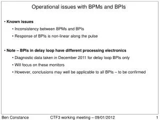
Operational issues with BPMs and BPIs • Known issues • Inconsistency between BPMs and BPIs • Response of BPIs is non-linear along the pulse • Note – BPIs in delay loop have different processing electronics • Diagnostic data taken in December 2011 for delay loop BPIs only • Will focus on these monitors • However, conclusions may well be applicable to all BPIs – to be confirmed Ben Constance CTF3 working meeting – 09/01/2012 1
Example – transmission along machine • Tobias 2011, analysis of current losses • Red asterisks mark BPIs, other monitors are BPMs • Typical transmission to TBTS Ben Constance CTF3 working meeting – 09/01/2012 2
Example – non-linear BPIs vs. BPMs in combiner ring Ben Constance CTF3 working meeting – 09/01/2012 3
Example delay loop BPI signals Exponential tail • Observation of delay loop signals December 2011 • Log raw electrode signals (decouple beam offset, current) • Droop on individual strip signals seen to be approximately exponential • Strips have different time constants • Time constants are dependent on the signal level Ben Constance CTF3 working meeting – 09/01/2012 4
Offline BPI signal processing • Signal processing is as follows: • where the signals have had their pedestal subtracted • Summation over signals with differing time constants • The droop on the current/position measurements is nota pure exponential • Any correction should be done on an individual electrode basis • Used least square fitting to measure decay time constants • However, poor fits to signals with larger time constants due to limited range of exponential tail (see next plot) • No obvious parameterisation Ben Constance CTF3 working meeting – 09/01/2012 5
Time constant vs. signal strength for all DL BPIs Ben Constance CTF3 working meeting – 09/01/2012 6
Consistency between BPM and BPI current measurement • Not simply a calibration issue • The delay loop BPIs give decaying sum signals • Similar non-linearity observed in BPIs elsewhere • Typically, signals are averaged over a window • Absolute recorded current dependent on window position and size • Ideally, would like to correct for non-linearity before calibration Ben Constance CTF3 working meeting – 09/01/2012 7
Droop correction by IIR filter • Can correct an exponential droop with an IIR filter: • where Vnis the nthsample andλ = 1/τis the decay constant • Pragmatic approach to filtering • Least square fit to the signal exponential tail • Fit for each electrode on a pulse-to-pulse basis • Fast fitting by linearisation and direct calculation of time constant • For N samples of the exponential tail at times tn, the least sq. estimate of τis: • Algorithm is fast • Would expect approximately double total signal processing latency Ben Constance CTF3 working meeting – 09/01/2012 8
Offline processing using fast algorithm • Top-left electrode signals for all DL BPIs, averaged over ~50 pulses: • Smaller time constants are well corrected, larger time constant signals aren’t • Slowly decaying signals’ tails do not go to zero • Again, due to insufficient length of exponential tail Ben Constance CTF3 working meeting – 09/01/2012 9
Significant effect on position signals (well corrected signals) Ben Constance CTF3 working meeting – 09/01/2012 10
Conclusions and further work • BPI non-linearity has significant impact on measured current and position • Desirable to correct this. IIR filter could potentially do so • Parameterisation of each electrode’s response non-trivial • Overcome by real-time fitting to exponential tail of signal • Currently, DL ADC gates do not sample enough tail for good correction • Shifting gate time to sample less baseline, more tail should work for DL • Extend gate length? • Must consider robustness if implementing in, for example, BPI driver • Must work for different pulse lengths (pedestal subtraction, location of tail) • Check applicability to TL1/CR/TL2 BPIs • Different processing electronics and higher beam current • Diagnostic data required to say more about these • Any changes to BPI processing should be followed by calibration Ben Constance CTF3 working meeting – 09/01/2012 11
Example filtered signals Ben Constance CTF3 working meeting – 09/01/2012 I
Effect on sum signals • Note: calibrated empirically with respect to treated signals Ben Constance CTF3 working meeting – 09/01/2012 II
Monte Carlo exponential fits • Fast fit to simulated, noisy exponential • RMS noise 2% of initial signal level • Vary range of simulated data used in fit from 10 – 100% of the time constant • Plot the fitted time constant as percentage of real value (with std. error) • Bad fit when droop is comparable to noise or any systematic ‘overshoot’ • When fit range is small compared to time constant, fit tends to over-estimate Ben Constance CTF3 working meeting – 09/01/2012 III
Possible solutions • Range of tail is 10 – 30% of the various observed time constants • Clearly too small a range for reliable time constant fitting • Contributing to (or explaining) the apparent nonlinearity in time constant vs. signal level • 1. Shift the gate timing to observe more tail • Currently ~150 samples of baseline before signal which could be used • Gives tail range of 40 – 100% of time constant, and likely accurate fitting • Would this ruin pedestal subtraction? How does the current algorithm work? • Extend the gate • Could we do the same as we did for the CR and observe more tail? • 3. Parameterise… Ben Constance CTF3 working meeting – 09/01/2012 IV
Possibility of parameterisation (for DL) • Much of the apparent nonlinearity (time constant vs. signal level) may be an artefact due to poor fits • Observing longer tail may allow decent parameterisation • Need to parameterise time constant vs. signal level by calibration • In absence of variable high current supply, must be beam based: • Short pulse would allow more tail to be observed • Generate two or three 1.5 GHz beams with different capture efficiencies • Inject satellites and inject mains into DL • Should give a good range of signal levels Ben Constance CTF3 working meeting – 09/01/2012 V