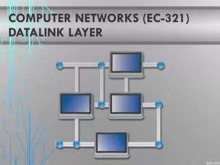
DataLink Layer
DataLink Layer. Pendahuluan. Merupakan Layer 2 pada Model OSI Bertujuan menyediakan koneksi antara dua komputer/host dengan menggunakan pengalamatan secara fisik/Hardware Addressing Komunikasi hanya bisa terjadi jika kedua host/komputer yang berkomunikasi tahu alamat fisik masing-masing

DataLink Layer
E N D
Presentation Transcript
Pendahuluan • Merupakan Layer 2 pada Model OSI • Bertujuan menyediakan koneksi antara dua komputer/host dengan menggunakan pengalamatan secara fisik/Hardware Addressing • Komunikasi hanya bisa terjadi jika kedua host/komputer yang berkomunikasi tahu alamat fisik masing-masing • Pengalamatan secara fisik biasa disebut MAC Address • MAC Address Diambilkan dari ID NIC masing-masing komputer
MAC (Media Access Control) Address • MAC Address terdiri dari 48 bit tetapi biasanya ditulis dalam 12 bit Heksadesimal dengan ketentuan 6 bit sebagai kode pabrik yang ditentukan oleh IEEE dan 6 bit berikunya adalah nomor serial peralatan yang dikeluarkan oleh pabrik
Pengiriman Data • Untuk melakukan pengiriman data diperlukan kombinasi antara pengalamatan secara fisik dan pengalamatan secara logik • pengalamatan secara logik biasa disebut dengan IP Address (nomor IP), berada pada layer network • Nomor IP diperlukan oleh perangkat lunak untuk mengidentifikasi komputer pada jaringan • Namun nomor identitas yang sebenarnya diatur oleh NIC (Network Interface Card) atau kartu Jaringan yang juga mempunyai nomor unik.
Pengiriman data pada DataLink Layer • Penentuan waktu pengiriman data yang tepat apabila suatu media sedang terpakai, hal ini perlu melakukan suatu deteksi sinyal pembawa. • Pada Ethernet menggunakan metode Carrier Sense Multiple Access / Collision Detection (CSMA/CD). • Pada jaringan yang dapat melakukan akses secara bersamaan simultan. Maka bila Host A mengirimkan data ke Host D, maka Host B dan C akan melakukan deteksi jalur, dan apabila jalur sedang dipakai maka Host B dan C akan menunggu terlebih dahulu.
Metode CSMA/CD • sebuah host komputer yang akan mengirim data ke jaringan pertama-tama memastikan bahwa jaringan sedang tidak dipakai untuk transfer dari dan oleh host komputer lainnya (Listen). • Jika pada tahap pengecekan ditemukan transmisi data lain dan terjadi tabrakan (collision), maka host komputer tersebut diharuskan mengulang permohonan (request) pengiriman pada selang waktu berikutnya yang dilakukan secara acak (random). • Dengan demikian maka jaringan efektif bisa digunakan secara bergantian
Error Checking Pengiriman Data • Data-Link dapat melakukan deteksi error dan memberikan peringatan (notification) kepada lapisan diatasnya,bahwa terjadi kesalahan transmisi. • Teknik yang digunakan error ddetection adalah Frame Check Sequence (FCS) dan Cyclic Redundancy Check (CRC). • Data Link tidak melakukan error-correction
Generic Data Link Frame Format Preamble or Start Field • When computers are connected to a physical medium, there must be a way they can grab the attention of other computers to broadcast the message, "Here comes a frame!" • Various technologies have different ways of doing this process, but all frames, regardless of technology, have a beginning signaling sequence of bytes. • Depending up frame format: Preamble = 7 bytes, Start or Start of Frame Delimiter (SFD) = 1 byte
Generic Data Link Frame Format Address Field • We saw how IEEE 802.3 uses Destination and Source Addresses. • By the way: Any idea how a serial data link frame is addressed? • Unicast address – Single device • Broadcast address – All devices • Multicast address – Specific group of devices
Generic Data Link Frame Format Type Field • Usually information indicating the layer 3 protocols in the data field, I.e. IP Packet. • Type field values of particular note for IEEE 802.3 frames include: • 0x0600 XNS (Xerox) • 0x0800 IP (the Internet protocol) • 0x8137 Novell NetWare packet formatted for Ethernet II • 0x6003 DECNET
“Ethernet” Frame Formats Length Field • In some frame formats such as 802.3, there is a length field which specifies the exact length of a frame. 802.3 802.3 802.2
IEEE 802.3 specification limits the data portion to a maximum of 1500 bytes. • Designed to hold a Layer 3 IP packet. • When IEEE created 802.2, it saw the need for a protocol TYPE field that identified what was inside the “data” field. • IEEE called its 1 byte type field DSAP (Destination Service Access Point). • Turned out that 1 byte was not long enough to handle all the different number of protocols.
To accommodate more protocols IEEE added the SNAP (Subnetwork Access Protocol) header.
The fields of various Ethernet framing that are used for identifying the type of data contained in a frame: • Ethernet II or DIX (DEC, Intel, Xerox) – Most common • IEEE Ethernet (802.3) • IEEE 802.3 with SNAP header
Generic Data Link Frame Format Data Field • Included along with this data, you must also send a few other bytes. • They are called padding bytes, and are sometimes added so that the frames have a minimum length for timing purposes. • LLC bytes are also included with the data field in the IEEE standard frames. (later)
Data Encapsulation Example Application Header + data Application Layer Layer 4: Transport Layer Layer 3: Network Layer Layer 2: Network Layer 010010100100100100111010010001101000… Layer 1: Physical Layer
Generic Data Link Frame Format FCS • Used to insure that the data has arrived without corruption. • More efficient than sending the data twice and comparing the results. • Necessary to prevent errors.
Three Kinds of FCS • Cyclic redundancy check (CRC) • performs polynomial calculations on the data • Two-dimensional parity • adds an 8th bit that makes an 8-bit sequence have an odd or even number of binary 1s • Internet checksum • adds the numbers to determine a number
Generic Data Link Frame Format Stop Field (Other data link frame formats) • The computer that transmits data must get the attention of other devices, in order to start a frame, and then claim it again, to end the frame. • The length field implies the end, and the frame is considered ended after the FCS. • Sometimes there is a formal byte sequence referred to as an end-frame delimiter.