Download
1 / 76
760 likes | 984 Vues
Instructions: Language of the Computer. Chapter 2 Sections 2.1 – 2.10 Based on slides from Dr. Iyad F. Jafar. Outline. The Von Neumann Architecture Busses & Memory Program Execution The Computer Language Instruction Set Architecture The MIPS ISA MIPS Design Principles

E N D
Instructions: Language of the Computer Chapter 2 Sections 2.1 – 2.10 Based on slides from Dr. Iyad F. Jafar
Outline • The Von Neumann Architecture • Busses & Memory • Program Execution • The Computer Language • Instruction Set Architecture • The MIPS ISA • MIPS Design Principles • Fallacies and Pitfalls • Further Reading • More Examples
The Von Neumann Architecture • John Von Neumann,1945 • A computer consists of • Processor • Memory • Input and Output • Stored-program concept as opposed to program-controlled computers ! • Programs and data are loaded into memory prior to execution • Different components are connected via set of shared wires called Busses for information exchange • Compare to Harvard Architecture! Processor Devices Datapath Input Memory Control Output
Busses • In any computer, there is usually three types of busses • Data • Used to exchange data between components • Bidirectional • Typical size 8, 16, 32, and 64 bits • Address • Used to specify the source/destination • Unidirectional • The size of the bus specifies the number of entities (memory locations,I/O) that can be addressed • Control • Used to specify the operation requested by the CPU (READ, WRITE, and other handshaking operations)
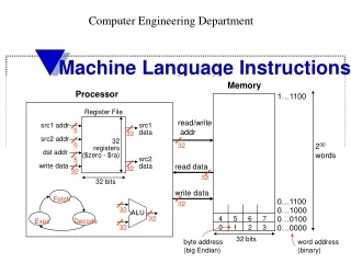
Memory 0 M-1 Bn-1 B1 B0 Data (n bits) 2 Bn-1 B1 B0 Address (Log2 M bits) 1 Bn-1 B1 B0 0 Bn-1 B1 B0 n bits (Memory Width) Control
Program Execution • Program = Instructions + Data • Programs are loaded into memory prior to execution • In order to execute the instructions, the CPU • Fetches the instruction • Read the instruction from memory (Control Unit) • Decodes the instruction • Understand what should be done (Control Unit) • Executes the instruction • Perform the required task (Datapath) • This is done repeatedly until the end of program ! Fetch Decode Execute
The Computer Language Suppose we want to perform two operations Add two numbers X and Y and store the result in Z Assign element 5 from array ARR to W • Commanding computers requires speaking their language; Binary electric signals at the hardware level (Machine Language) • Tedious, time consuming, error-prone, knowledge about processor architecture • Make it easier! • Represent binary instruction by words (Assembly Language). • Convert words to binary manually or using Assemblers • Tedious, time consuming, error-prone, knowledge about processor architecture • One line corresponds to one instruction!! • Make it even easier! • Make expressing instructions closer to the way humans express operations (High-level Languages) • Conversion to machine language is done automatically using Compilers 00001 0011 0001 0010 00101 0010 0000 0111 ADD Z, X, Y READ W, ARR[5] Z = X + Y W = ARR[5]
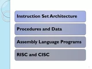
Instruction Set Architecture • Designing processors requires specifying the type and number of instructions the processor is supposed to support and how a programmer can use it • This is specified by the instruction set architecture (ISA) of the processor which includes • Instructions (type, encoding, operation …) • Memory and I/O access • Registers (Why do we need registers !) • Different processors have different ISA • IA-32, MIPS, SPARC, ARM, DEC, HP, IBM, … • The same ISA can be implemented in different ways to achieve different goals • Single-cycle, multi-cycle, pipelining, …
Instruction Set Architecture • Generally, the design of ISA could follow one of two schools • CISC - Complex Instruction Set Computers • RISC - Reduced Instruction Set Computers (~1980s )
The MIPS ISA • Historical Facts • Microprocessor without Interlocked Pipeline Stages • First MIPS processor by John Hennessey in 1981 at Stanford University • MIPS Technologies, Inc. 1984 • First commercial model R2000 1985 • General Features • RISC • 32-bit and 64-bit • Register-Register Architecture (Load-Store) • ISA revisions MIPS I, MIPS II, MIPS III, MIPS IV, MIPS V, MIPS32, and MIPS64 • Different processor models R2000, R3000, R4000, R10000
The MIPS ISA – Register File 5 0 Read Addr 1 31 B31 B1 B0 5 32 Read Addr 2 Read Data 1 5 Write Addr 32 2 B31 B1 B0 32 Read Data 2 Write Data 1 B31 B1 B0 0 B31 B1 B0 Read/Write 32 bits • Inside the CPU • SRAM !! • Hold data temporarily • Some sort of caching of data • Why two read ports ?
The MIPS ISA – Register File • When writing assembly, these registers can be referenced by their address (number) or name • General purpose and special purpose registers
The MIPS ISA – Register File • There are other registers ! • Not directly accessible (no address) • PC: Program counter • Instruction sequencing • LO and HI • Used with multiplication and division instructions PC LO HI 32 bits
The MIPS ISA - Instructions • Different categories • Arithmetic, logical, memory, flow control • All instructions are encoded in binary using 32 bits (Fixed Size!!!) • Three different formats depending on the number and type of operands, and operation • R-type • I-type • J-type • Instruction encoding • Opcode operation code that specifies the operation in binary • Operands the ins and outs of the instruction
The MIPS ISA - Instructions • Arithmetic instructions A = B + C ADD A, B, C ADD $s0, $s1, $s2 #$s0 = $s1 + $s2 F = C - A SUB F, C, A SUB $t2, $s6, $s4 #$t2 = $s6 - $s4 Operation Destination, Source1, Source2 destination source1 op source2 • Each arithmetic instruction performs one operation • Each instruction has three operands • The operands are in the file registers of the datapath • The order of operands is fixed
The MIPS ISA - Instructions • Arithmetic instructions • Example 1. • Given the following piece of C code, find the equivalent assembly code using the basic MIPS ISA given so far. a = b – c d = 3 * a Solution:assume that the variables a, b, c, and d are associated with registers $s0, $s1, $s2, and $s3, respectively, by the compiler. sub $s0, $s1, $s2 # $s0 contains b – c add $s3, $s0 ,$s0 # $s3 contains 2*a add $s3, $s3, $s0 # $s3 contains 3*a
The MIPS ISA - Instructions • Arithmetic instructions • Example 2. • Given the following piece of C code, find the equivalent assembly code using the basic MIPS ISA given so far. f = (g + h) – (i + j) Solution: assume that the variables f, g, h, i, and j are associated with registers $s0, $s1, $s2, $s3, and $s4, respectively, by the compiler. add $t0, $s1, $s2 # $t0 contains g + h add $t1, $s3 ,$s4 # $t1 contains i + j sub $s0, $t0, $t1 # $s0 contains (g+h) – (i+j) More efficient translation!???
The MIPS ISA - Instructions • Arithmetic Instructions Machine Language • Any instruction has to be encoded using 32 bits including the operation and its operands ADD $t0, $s1, $s4 op rs rt rd shamt funct R-type 6 5 5 5 5 6 op 6-bits opcode that specifies the operation rs 5-bits register file address of the first source operand rt 5-bits register file address of the second source operand rd 5-bits register file address of the result’s destination shamt 5-bits shift amount (for shift instructions) funct 6-bits function code augmenting the opcode
The MIPS ISA - Instructions • Arithmetic Instructions Machine Language • Example 3. What is the machine code for ADD $s0, $t0, $s4 s ADD $s0, $t0, $s4 000000 01000 10100 10000 00000 100000 6 5 5 5 5 6 0000 0001 0001 0100 1000 0000 0010 0000 B 0 1 1 4 8 0 2 0 H
The MIPS ISA - Instructions • Arithmetic Instructions Machine Language • Example 4. What is the machine code for SUB $s1, $s2, $s3 s SUB $s1, $s2, $s3 000000 10010 10011 10001 00000 100010 6 5 5 5 5 6 0000 0010 0101 0011 1000 1000 0010 0010 B 0 2 5 3 8 8 2 2 H
The MIPS ISA - Instructions • Logical Instructions • AND, OR, NOR • Operation is performed between corresponding bits (bitwise) • R-type instruction format • Example 5. What is the machine code for AND $s1, $t2, $s2 op = 0x0 rs = $t2 = 0x0A rt = $s2= 0x12 rd = $s1 = 0x11 shamt= 0x00 funct= 0x24 AND $s4, $s3, $t4 # $s4 = $s3 & $t4 OR $s0, $t7, $s3 # $s0 = $t7 | $s3 NOR $s2, $t6, $s3 # $s2 = ~($t6 | $s3)
The MIPS ISA - Instructions • Arithmetic and Logic Instructions with Immediate • In many occasions, we encounter high-level statements such as • X = Y + 5 • Z = W – 4 • F = 514 x R • If (C>-3) … • This implies that the operation is between a register and some constant ! • Can we do this with ADD and SUB instructions? • Where do these constants come from? • MIPS ISA specifies a new set of instructions that deal with immediate data • ADDI, ORI, ANDI, XORI, …
The MIPS ISA - Instructions • Arithmetic and Logic Instructions with Immediate ADDI $t5, $s3, 130 ADDIU $s1, $s2, 15 op rs rt Immediate I-type 16 6 5 5 Immediate Addressing! Sign Extension 16 Instruction 32 Register File Reg[rs] +
The MIPS ISA - Instructions • Arithmetic and Logic Instructions with Immediate ANDI $t1, $t3, 12 ORI $s3, $a0, 123 op rs rt Immediate I-type 16 6 5 5 Immediate Addressing! Zero Extension 16 Instruction 32 Register File Reg[rs] &
The MIPS ISA - Instructions • Arithmetic and Logic Instructions with Immediate • What if the immediate is greater than 16 bits? • In MIPS, this is achieved in two steps using the Load Upper Immediate (LUI) and ORI instructions • Suppose we want to add the constant • (0000 0010 0100 0010 0001 0011 1100 1100)2 to $s0 LUI $t0, 1000 1111 0001 0010 # loads the upper 16 bits of $t0 and sets the lower 16 bits to 0 LUI $t0, (0000 0010 0100 0010)2 ORI $at, $t0, (0001 0011 1100 1100)2
The MIPS ISA - Instructions • Memory instructions • MIPS ISA address bus is 32 bits, i.e. it can address up to 232 (4 G) locations • Memory width is usually 8 bits (byte) 0xFF FF FFFF Address Bus (32 bits) MIPS CPU 32-bit Data Bus (32 bits) Read Write 0x00 00 00 02 0x00 00 00 01 0x00 00 00 00 8 bits
The MIPS ISA - Instructions • Memory instructions • Most memories are byte addressable ! • Every four consecutive locations (8 bits each) form a word (32 bits) ! • In other words, the addresses of two consecutive locations differ by 4 0x00 00 00 0E 0x00 00 00 0D 0x00 00 00 0C 0x00 00 00 0B 0x00 00 00 0A 0x00 00 00 09 0x00 00 00 20 0x00 00 00 08 0x00 00 00 1C 0x00 00 00 07 0x00 00 00 18 0x00 00 00 06 0x00 00 00 14 0x00 00 00 05 0x00 00 00 10 0x00 00 00 04 0x00 00 00 0C 0x00 00 00 03 0x00 00 00 08 0x00 00 00 02 0x00 00 00 04 0x00 00 00 01 0x00 00 00 00 0x00 00 00 00 8 bits 32 bits
The MIPS ISA - Instructions • Memory instructions • Reading from memory requires specifying the address to read from and a register to store the read data • Writing to memory requires specifying an address to write to and a register whose content will be written to memory • Simple ! However, addressing a memory location requires 32 bits • Where do these bits come from ?! • Are they stored in memory?! • Are they part of the instruction ?! • Displacement Addressing • In MIPS the address is formed by adding the content of some register (the base register) to 16-bit signed constant (offset or displacement) that is part of the instruction itself. • The offset is sign-extended to 32 bits to match the size of the register.
The MIPS ISA - Instructions • Memory instructions • The Load instruction – reads 32 bit value (A word) into a register lw $t0 , 4 ($s4) Operation Destination Offset Base Register Reg[$t0] = MEM[Reg[$s4]+sign_extend(4)] Memory Data Register File Memory 32 Register Content Address + 32 32 32 16 Sign Extension Instruction offset
The MIPS ISA - Instructions • Memory instructions • The Store instruction – writes the 32 bits (A word) found in a register into a memory location sw $t5 , -12 ($t1) Nemunic Destination Offset Base Register MEM[Reg[$t1]+sign_extend(-12)] = Reg[$t5] Register Content Register File Memory 32 Register Content Address + 32 32 32 16 Sign Extension Instruction offset
The MIPS ISA - Instructions • Memory instructions • The memory is byte-addressable. • However, the load and store instructions deal with words (4 bytes)! • Reading from memory is effectively reading four bytes! How these bytes are ordered in the 32 bit register ? • Storing to memory is storing 32 bits in four consecutive locations. What is the order by which these bits are stored in 4 different locations? • Two approaches • Little endian: the least significant byte is associated with the location of lowest address (Intel) • Big endian: the most significant byte is associated with the lowest address (MIPS)
The MIPS ISA - Instructions Register Reading a word from memory Byte 3 Byte 2 Byte 1 Byte 0 0xFD 0x43 0x33 0x10 Little Endian Memory 32 bits 0xFD 0x00 00 00 F5 0x00 00 00 F4 0x43 0x00 00 00 F3 0x33 0x10 0x00 00 00 F2 Register Byte 3 Byte 2 Byte 1 Byte 0 0x10 0x33 0x43 0xFD Big Endian 8 bits 32 bits
The MIPS ISA - Instructions • Memory Instructions • Example 7. Convert the following high-level statements to MIPS assembly language G = 2 * F A[17] = A[16] + G Solution assume that the variables F and G are associated with registers $s4 and $s5, respectively, and the base address of the array A is in $s0. All values are 32-bit integers. add $s5, $s4, $s4 # $s5 contains 2*F lw $t0, 64($s0) # $t0 contains A[16] (note the offset is 64) add $t0, $t0, $s5 # $t0 contains A[16] + G sw $t0, 68($s0) # store $t0 in A[17] (note the offset is 68)
The MIPS ISA - Instructions • Memory Instructions - Machine Language lw $t0, 4 ($s4) sw $t2, -6 ($at) op rs rt Offset (displacement) I-type 6 5 5 16 op 6-bits opcode that specifies the operation rs 5-bits register file address containing the base address rt 5-bits register file address of destination register (LW) or the source register (SW) Offset 16-bits displacement or offset (number of bytes to move, positive or negative) How far can we move in memory when using LW and SW?
The MIPS ISA - Instructions • Memory Instructions • Example 6 • Machine code for lw $s5, 4($s1) in hexadecimal op= 0x23 rs = $s1 = 0x11 rt = $s5 = 0x15 offset = 0x0004 • Machine code for sw $s0, 16($s4) in hexadecimal op = 0x2b rs = $s4 = 0x14 rt = $s0 = 0x10 offset =0x0010
The MIPS ISA - Instructions • Memory Instructions • MIPS ISA defines memory instructions that can load/store bytes (8 bits) and half words (16 bits) lb $t0, 1($s3) #load byte from memory (sign extention) lbu $t0, 1($s3) #load byte from memory (zeros extension) sb $t0, 6($s3) #store byte to memory lh $t0, 1($s3) #load half word from memory (sign extension) lhu $t0, 1($s3) #load half word from memory (sign extension) sh $t0, 6($s3) #store half word to memory • When loading a byte into 32-bit register, where is it stored? • Lower 8 bits of the register ! What about remaining bits? • When loading a half word into 32-bit register, where is it stored? • Lower 16 bits of the register ! What about remaining bits? • How about sb and shinstructions?
The MIPS ISA - Instructions • Memory Instructions LBU $s0, 2 ($s4) # assume Reg[$s4] = 0x00 00 00 F0 Memory Byte 3 Byte 2 Byte 1 Byte 0 0x00 0x00 0x00 0xD0 $s0 0xFD 0x00 00 00 F5 32 bits 0x00 00 00 F4 0x43 0x00 00 00 F3 0xC3 0xD0 0x00 00 00 F2 LB $s0, 2 ($s4) # assume Reg[$s4] = 0x00 00 00 F0 0x00 00 00 F1 0x30 0x00 00 00 F0 0x04 Byte 3 Byte 2 Byte 1 Byte 0 0xFF 0xFF 0xFF 0xD0 $s0 8 bits 32 bits What if the instructions are LH and LHU?
The MIPS ISA - Instructions • Flow Control Instructions • Instructions are loaded in memory! • The normal execution of programs is sequential; one instruction after another! • Keeping track of execution is done through a special register called the Program Counter (PC) • 32 bits (Why???) • It is incremented automatically by 4 (why!) after an instruction is fetched • Thus, its contents always holds the address of the next instruction! • It is not directly accessible !!! (Why) • However, in our programs, we often write statements that skip some parts of the program, conditionally or unconditionally !! (IF, SWITCH, WHILE, GOTO … ) • How is this implemented in the hardware !?
The MIPS ISA - Instructions • Flow Control Instructions • How to skip instructions in memory to execute others? • Basically, this requires using instructions that change the contents of the PC to point to the address where the target instructions are loaded (branch/jump address)! • In MIPS, there are no instructions that can modify the PC directly! • Alternatively, we have two conditionaland three unconditional flow control instructions! • These instructions can change the contents of the PC indirectly!
The MIPS ISA - Instructions • Conditional Flow Control Instructions • Branch If Equal Instruction (BEQ) • Checks if two registers are equal! • If true, then the PC (containing the address of next instruction) is incremented or decremented by adding a signed 16-bit offset (that is part of the instruction) after it is multiplied by 4 (WHY?). • If false, program execution continues normally from the address in PC. • This is called PC-relative addressing! BEQ $t0 , $t1, 15 Tested Registers Offset Operation
The MIPS ISA - Instructions • Conditional Flow Control Instructions • Branch If Equal Instruction (BEQ) =? Reg1 Reg2 MEM MUX BEQ PC …. Sign Extension Branch Address + …. Address of instruction following BEQ x4 16 bit offset 32 bit instruction from branch address (two registers are equal) Instruction 32 bit instruction next to BEQ (Two registers are not equal)
The MIPS ISA - Instructions • Conditional Flow Control Instructions • Branch If Not Equal Instruction (BNE) • Checks if two registers are not equal! • If true, then the PC (containing the address of next instruction) is incremented or decremented by adding a signed 16-bit offset (that is part of the instruction) after it is multiplied by 4 (WHY?)). • If false, program execution continues normally from the address in PC. • This is called PC-relative addressing! BNE $t0 , $t1, -23 Tested Registers Offset Operation
The MIPS ISA - Instructions • Flow Control Instructions (Conditional) • Branch If Not Equal Instruction (BNE) =? Reg1 Reg2 MEM MUX BNE Branch Address PC …. Sign Extension + …. Address of instruction following BNE x4 16 bit offset 32 bit instruction from branch address (Two registers are not equal) Instruction 32 bit instruction next to BNE (Two registers are equal)
The MIPS ISA - Instructions • Flow Control Instructions • Example 8. Convert the following high-level statements to MIPS assembly language if (x == y) x = x + y end Solution assume that the variables x and y are associated with registers $s4 and $s5, respectively. BNE $s4, $s5, 1# if $s5 ~= $s4, skip one instruction ADD $s4, $s4, $s5 # add x and y if they are equal … OR, we can use labels instead of counting how many instructions to skip! BNE $s4, $s5, SKIP# if $s5 ~= $s4, skip one instruction ADD $s4, $s4, $s5 # add x and y if they are equal SKIP: ….
The MIPS ISA - Instructions • Flow Control Instructions -Machine Language BEQ $t0, $t1 , 4 BNE $t2, $v1, -214 op rs rt Offset (displacement) I-type 6 5 5 16 op 6-bits opcode that specifies the operation rs 5-bits first register file address to be compared rt 5-bits second register file address to be compared Offset 16-bits displacement or offset (number of instructions to skip, positive or negative!) How many instructions can we skip when using BNE and BEQ?
The MIPS ISA - Instructions • Conditional Flow Control Instructions • Example 9. • Machine code for BEQ $s5, $s1, 20in hexadecimal. op = 0x04 rs = $s5 = 0x15 rt = $s1 = 0x11 offset =0x0014 • Machine code for BNE $s0, $s1, -13 in hexadecimal op = 0x05 rs = $s0 = 0x10 rt = $s1 = 0x11 offset = 0xFFFD
The MIPS ISA - Instructions • Conditional Flow Control Instructions • BEQ and BNE instructions can check for equality only? • How about > , < , <= , >= ??? • There are no instructions such bgt, bls, bge, ble!! • In MIPS ISA, this can be done with the aid of • The Set On Less than Instructions (SLT and SLTU) • Compares if one register is less than another one • If so, a third register is loaded with 1 • Otherwise, the third register is loaded with 0 • The $Zero register • Register number zero • Hardwired to zero • Can be read only!
The MIPS ISA - Instructions • Conditional Flow Control Instructions • SLT Instruction SLT $s1, $s2, $s3 #set $s1 if $s2 < $s3, else clear $s1 $S1 = 1 Yes $S2 $s2-$s3<0 ?? - $S3 $S1 = 0 No
The MIPS ISA - Instructions • Conditional Flow Control Instructions • SLT Instruction – Machine Language SLT $t0, $s1, $s4 op rs rt rd shamt funct R-type 6 5 5 5 5 6 • Opcode for SLT is 0x00 and the func field is 0x2a • How about comparing with constants? • SLTI • How about comparing unsigned numbers? • SLTU and SLTIU
The MIPS ISA - Instructions • Conditional Flow Control Instructions • So, how can we execute blt $s1, $s2, L1 ? • Such instructions are included in the ISA as pseudo instructions (fake). • The assembler takes the job of converting them to actual assembly instructions through using the $at register • How about other branch instructions? slt$at, $s1, $s2 bne$at, $zero, L1 ………. ………. L1: blt $s1, $s2, L1 ………. ………. L1: