Understanding MIPS Assembly Language and Register File
Learn the fundamentals of MIPS assembly language, processor architecture, and register file operations. Explore arithmetic and data access instructions, operand handling, memory access, and more in this comprehensive guide.

Understanding MIPS Assembly Language and Register File
E N D
Presentation Transcript
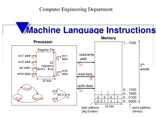
Memory Processor 1…1100 Register File read/write addr src1 addr src1 data 5 32 src2 addr 32 registers ($zero - $ra) 5 32 230 words dst addr 5 src2 data read data write data 32 32 32 32 bits write data Fetch 0…1100 32 32 0…1000 ALU 32 4 5 6 7 0…0100 32 0 1 2 3 0…0000 Exec Decode 32 bits byte address (big Endian) word address (binary) Computer Engineering Department Machine Language Instructions
Assembly Language • Language of the machine • More primitive than higher level languages e.g., no sophisticated control flow • Very restrictive e.g., MIPS arithmetic instructions • We’ll be working with the MIPS instruction set architecture • similar to other architectures developed since the 1980's • used by Intel, NEC, Nintendo, Silicon Graphics, Sony, … • 32-bit architecture • 32 bit data line and address line • data and addresses are 32-bit
Assembly Language • MIPS favors simplicity – each line in the program is an instruction. • There are several categories of instructions: • Some are “register type” or R-type (such as arithmetic operations) and • Some are “Data access type” or I-type (lw, sw) – involve memory access. • All instructions are represented as 32-bit binary numbers, but the significance of the bits differs depending on the instruction category (as we’ll see later).
Arithmetic instructions • MIPS assembly language arithmetic statement (like add a, b, c #a=b+c) • add $t0, $s1, $s2 • sub $t0, $s1, $s2 • Each arithmetic instruction performs only one operation • Each arithmetic instruction specifies exactly three operands • destination source1 op source2 op • Those operands are contained in the datapath’s register file ($t0, $s1, $s2) • Operand order is fixed (destination first)
More complex instructions • Example The C statement f = (g+h) – (i+j); If variable values are stored in registers f g h i j $s0 $s1 $s2 $s3 $s4 Then the same statement can be re-written in MIPS assembly as add $t0, $s1, $s2 #$t0=g+h add $t1, $s3, $s4 #$t1=i+j sub $s0, $t0, $t1 #$s0=f
Operands and Registers • Operands are stored in Registers (memory locations visible to the programmer) • Registers are • Faster than main memory • Can hold variables so that • code density improves (since registers are named with fewer bits than a memory location) • – why is that? • Register addresses are indicated by using $ followed by two characters (like $t0)
5 5 5 32 32 32 Register File src1 addr src1 data src2 addr 32 locations dst addr src2 data write data 32 bits MIPS Register File • Operands of arithmetic instructions must be from a limited number of special locations contained in the datapath’s register file (inside the CPU) • Holds thirty-two 32-bit registers • With two read ports and • One write port
Name Convention for Registers 0 $zero constant 0 1 $at reserved for assembler 2 $v0 expression evaluation & 3 $v1 function results 4 $a0 argument registers 5 $a1 6 $a2 7 $a3 8 $t0temporary: caller saves . . . (callee can clobber) 15 $t7 Registers 0.. 15
Name Convention for Registers 16 $s0 callee saves . . . 18 $s2 23 $s7 24 $t8temporary (cont’d) 25 $t9 26 $k0 reserved for OS kernel 27 $k1 28 $gp pointer to global area 29 $sp stack pointer 30 $fp frame pointer 31 $ra return address Registers 16.. 31
Processor Devices Control Input Memory Datapath Output What happens for large arrays? • Arithmetic instructions operands must be registers, — only thirty-two registers provided • What about programs with lots of variables? • Store variables in memory • Load variables from memory to registers before use; store them back to memory after use.
Accessing Memory The data transfer instruction must specify • where in memory to read from (load) or write to (store) – memory address • where in the register file to write to (load) or read from (store) – register destination (source) • The memory address is formed by summing the constant portion of the instruction and the contents of the second register
Accessing Memory • MIPS has two basic data transfer instructions for accessing memory • lw $t0, 4($s3) #load word – read data from memory and place it in register $t0 • sw $t1, 8($s3) #store word – store data located in register $t1 to memory
32 32 32 read addr/ Processor Addressable locations read data Memory write data Addressing Memory • Memory is viewed as a large, single-dimension array, with an address • A memory address is an index into the array write addr 232 Q: what should be the smallest addressable unit?
Big endian Little endian Addressing Memory • Since 8-bit bytes are so useful, most architectures address individual bytes in memory • With 32-bit addressing – we can access 232 bytes • Architectures may be “Big endian” or “Little endian”
0 1 2 3 Aligned Not Aligned Addressing Memory • memory: 232 bytes = 230 words • Therefore, the memory address of a word must be a multiple of 4 (alignment restriction) Alignment restriction: requires that objects fall on an address that is multiple of their size.
Addressing Memory • The memory address is formed of a “base” address (stored in a register) and an offset. Since addresses differ by 4, so do the offsets (0, 4, 8, 12, …). The address of a word matches that of one of its bytes • Thus the memory address is formed by summing the constant portion of the instruction and the contents of the base register (the second register in the instruction)
Memory Word address . . . 0 1 1 0 24 . . . 0 1 0 1 20 $t1 . . . 1 1 0 0 16 . . . 0 0 0 1 12 $t0 . . . 0 0 1 0 8 . . . 1 0 0 0 4 Data . . . 0 1 0 0 0 Addressing Memory lw $t0, 4($s3) #what is loaded into $t0? sw $t1, 8($s3) #$t1 is stored where? If register $s3holds 8
A[4] $s3+16 A[3] $s3+12 A[2] $s3+8 A[1] $s3+4 A[0] $s3 Addressing arrays • Assume the C program contains the instruction • a = b + A[4] • $s1 $s2 $t0 First we load A[4] in a temporary register lw $t0, 16($s3) Then we add the contents of register $s2 add $s1, $s2, $t0
$s3+12 $s3+8 $s3+4 A[4] $s3+16 A[3] A[2] A[1] A[0] $s3 Addressing arrays • Now assume the C program contains the instruction • A[7] = a + A[4] • $s1 $t0 First we load A[4] in a temporary register as before lw $t0, 16($s3) Then we add the contents of registers add $t0, $t0, $s1 Finally, we store back in memory sw $t0, 28($s3)
$s3+8 $s3+4 A[i] $s3+4i ….. A[2] A[1] A[0] $s3 Addressing arrays • What if the array location is variable?, as in • g = A[i] • $s1 $s4, and $s3 holds the base address First we compute 4i doing two additions i + i = 2i; 2i + 2i = 4i Thus add $t1, $s4, $s4 add $t1, $t1, $t1 Then we compute the address add $t1, $t1, $s3 lw $s1, 0($t1)
Representing Instructions in Machine Language • Instructions, like registers and words of data, are also 32 bits long • They are formed by placing binary number “fields” side-by-side to form a 32 bit machine language instruction • The meaning of these bits (or the “format” of the instruction) depends on its type. • Instruction Format differs for R-type instructions (add, sub) vs. I-type instructions (lw, sw) – data access type
R-type 000000 op I-type (lw) op 100011 35 Machine LanguageInstructions • The first field is the op field (6 bits), which tells the processor what type of instructions this is • For R-type the op field is 0s, for lw it is binary equivalent of 35, for sw it is the binary equivalent of 43
First source operand Second source operand R-type op rs rt I-type op rs rt Register holding the memory address Destination register Machine LanguageInstructions • The second field is the rs field (5 bits long); • The third field (also 5 bits) is “rt” – it is the second source operand for R-type and the destination register for I-type
I-type op rs rt address 16-bit offset constant Machine LanguageInstructions • The last field in I-type operations is the 16 bit-long “address” offset field which is a constant. • that means the offset has a max value of 215(32,768 bytes) or 213words( 8,192 row locations)
43 18 8 24 101011 10010 01000 0000000000011000 op rs rt 16 bit number Machine LanguageInstructions • Example sw $t0, 24($s2) We know that $t0 is 8 and $s2 is 18, so Machine code
op rs rt rd shamt funct R-type Machine LanguageInstructions • The fourth field for R-type instructions is the rd field (5 bits), which is the destination operand – the name of the register where results are stored. • The fifth field is the unused “shift amount” (zeros); • The last field of 6 bits for R-type operations is the “function” field – tells the processor what kind of R-type operation to perform (it is 32 for add, 34 for sub, etc.)
000000 10001 10010 01000 00000 100010 op rs rt rd shamt funct Machine LanguageInstructions • What is the machine code for: sub$t0, $s1, $s2 #t0=s1-s2 • First we need the register addresses $t0, … $t7 and $s0 … $s7 in MIPS have addresses 8 … 15 16 … 23 • So rs=$S1=1710=1001; rt=$S2=1810=10010 rd=$t0=810=01000; funct=3410=100010
Memory Processor 1…1100 Register File read/write addr src1 addr src1 data 5 32 src2 addr 32 registers ($zero - $ra) 5 32 230 words dst addr 5 src2 data read data write data 32 32 32 32 bits write data Fetch 0…1100 32 32 0…1000 ALU 32 4 5 6 7 0…0100 32 0 1 2 3 0…0000 Exec Decode 32 bits byte address word address (binary) Instructions, so far • Arithmetic instructions – to/from the register file • Load/store word instructions – from/to memory
35 19 8 1200 43 19 8 1200 0 18 8 8 0 34 Machine LanguageInstructions • What is the machine code for A[300] = h – A[300] in C. Assume h is stored in $s2 and base address in $s3 • First the corresponding assembly code is lw$t0, 1200($s3) #t0 gets A[300] sub$t0, $s2, $t0 #t0 gets h-A[300] sw$t0, 1200($s3)#store t0 back in memory Intermediate decimal notation
100011 10011 01000 0000 0100 1011 0000 101011 10011 01000 0000 0100 1011 0000 Machine LanguageInstructions • What is the machine code for A[300] = h – A[300] in C? 000000 10010 01000 01000 00000 100010 • Instructions are numbers – can be stored in memory like data – “store program” concept
Logical operations • Operate on field of bits and on individual bits • Needed, for example when examining characters in a word, but also in multiplying numbers
sll srl R-type R-type 0 0 $t1 $t2 shift 0 0 0 $t1 $t2 shift 2 Logical Operations • Logical shift operations move all the bits of a word to the left or to the right a specified number of bits. The emptied bits are filled with 0s. It is an R-type instruction sll $t2, $t1, 4 #$t1<<4 • places in $t2 the contents of register $t1 shifted left by 4 bits. Consider the sequence: Ex. $t1 = 0000 0001… 0000 1111 $t2 = 0001… 1111 0000 after sll 4 $t2 = 0000… 0011 1100after srl 2
R-type 0 $t1 $t2 $t0 0 36 Logical Operations • To apply a bit pattern – to force 0s on a bit field and $t0, $t1, $t2 places in $t0 the logical AND of registers $t1 and $t2. • Logical and puts a 1 in the field where both$t1 and $t2 bits were 1s at that location • Example$t1 = 0000… 0000 1101 $t2 = 1000… 0000 1001 $t1&$t2= 0000… 0000 1001
R-type 0 $t1 $t2 $t0 0 37 Logical Operations • The dual of AND is OR or $t0, $t1, $t2 places in $t0 the logical or of contents of registers $t1 and $t2. • Logical or puts a 1 in the field where either$t1 and $t2 bits at that location were 1s • example $t1 = 0000… 0000 1101 $t2 = 1000… 0000 1001 $t1|$t2= 1000… 0000 1101
R-type 0 $t1 $t2 $t0 0 39 Logical Operations • NOT(A) places a 1 in result if A bit is 0 and places 0 in resultif A bit is 1. NOR is a MIPS instruction • A NOR 0 =NOT(A OR 0)= NOR (A) nor $t0, $t1, $t2 places in $t0 the logical nor of registers $t1 and $t2. • Logical nor (not or) puts a 0 in the field where either$t1 and $t2 bits were 1s • example $t1 = 0000… 0000 1101 $t2 = 1000… 0000 1001 ~($t1|$t2)= 0111… 1111 0010
I-type andi 12 $s2 $s1 constant I-type ori 13 $s2 $s1 constant LogicalInstructions • There are also immediate versions of logical operations andi $s1, $s2, 1000 ori $s1, $s2, 1000 • Places in register $s1 the and or the or of register $s2 with a 16-bit constant (the least significant bits are & or |). This works like a “mask” to cover or uncover fields. • ori is also used in conjunction with lui to load a 32-bit constant in a register • While and and or are R-type, andi and ori are I-type
Control Flow Instructions • Decision making instructions alter the control flow i.e., change the next instruction to be executed • Why do we need decision making instructions? if (i==j) h = i + j; • MIPS conditional branch instructions:bne$s0, $s1, Lab1 #go to Label1 if value stored in $s0$s1 beq$s0, $s1, Lab2 #go to Label2 if value stored in $s0 equal with that stored in $s1
5 bits 5 bits 6 bits I format bne 5 16 17 ???? 4 16 17 ???? beq op rs rt 16 bit number Conditional branch instructions • Recall that saved register $s0 corresponded to address 16 in register file and $s1 to address 17 • Machine Formats: • How is the branch destination address specified? Specifies the branch destination
bne $s0,$s1,Lab1 add $s3,$s0,$s1 Lab1: ... Specifying Branch Destinations • Could specify the memory address • but that would limit the program size to 216 instructions • How can conditional branches operate inside large programs? • We know that conditional branches typically go to addresses close to where the test was done.
bne $s0,$s1,Lab1 PC add $s3,$s0,$s1 Lab1+PC: ... Specifying Branch Destinations • MIPS architecture uses program counterPC-relative addressing • PC gets updated (PC+4) during the fetch cycle so that it holds the address of the next instruction • This allows jumps of –215 to 215 –1 from the next instruction after conditional branch
bne $s0,$s1,Lab1 PC add $s3,$s0,$s1 Lab1+PC: ... Specifying Branch Destinations • We can optimize since address is multiple of 4 (a word address) – • Since 410 in binary is 100, all word address have 00 as last two bits – 810 is 1000, 1210 is 1100, etc. • Optimization - right shift the offset by 2 bits (divided by 4), and store the value • Essentially, it can cover -217to +217-1 offset
from the low order 16 bits of the branch instruction Sign bit 16 offset sign-extend 00 branch dst address 32 32 Add Branch taken PC 32 32 Add 32 4 32 32 ? Computing Branch Destinations • The contents of PC+4 are added to the low order 16 bits of the branch instruction which is converted into a 32 bit value: concatenating two low-order zeros to create an 18 bit number • Then sign-extending those 18 bits • The result is written into the PC if the branch condition is true prior to the next Fetch cycle
$s0 Ss1 $t0 op rs rt rd shift funct R-type instruction 0 16 17 8 0 42 More control flow instructions • We have beq, bne, but what about branch-if-less-than? • New R-type instruction called “set on less than” slt $t0, $s0, $s1 • if value stored in $s0 is less than the value stored in $s1 then set contents of $t0 to 1 else set $t0 = 0
Other Branch Instructions • Can use slt, beq, bne, and the fixed value of 0 in register $zero to create all relative conditions less than blt $s1, $s2, Label less than or equal to ble $s1, $s2, Label greater than bgt $s1, $s2, Label great than or equal to bge $s1, $s2, Label • These are pseudo instructions recognized (and expanded) by the assembler • The assembler needs a reserved register ($at) there are policy of use conventions for registers
Pseudo Instructions • Example - produce a minimal sequence of actual MIPS instructions to accomplish what the pseudo instruction means to do: ble $t5, $t3, Label #if number in $t5 is number in $t3, branch to Label • The equivalent MIPS instructions are: slt $at, $t3, $t5 #if $t3<$t5, $at=1 beq $at, $zero, Label • Another pseudo instruction bgt $t5, $t3, Label #if number in $t5 is > number in $t3, branch to Label • The equivalent MIPS instructions are: slt $at, $t3, $t5 #if $t3<$t5, $at=1 bne $at, $zero, Label
Jformat op 26-bit address 2 ???? Unconditional branch instructions • There are two types: jump instruction:j exit #go to the statement with label “exit” • Machine Format: • How is the jump destination address specified?
from the low order 26 bits of the jump instruction 26 00 4 32 PC 32 Computing Jump Destination • Is an absolute address formed by concatenating the upper 4 bits of the current PC (now PC+4) to the 26-bit address and concatenating 00 as the 2 low-order bits • Creates a 32 bit instruction address that is placed into the PC prior to the next Fetch cycle (no testing)
op $t1 0 0 0 funct Rformat 0 9 0 0 0 8 Jump instructions - continued • Instruction: jump register instruction • jr $t1 #go to the address stored in register $t1 • Machine Format: • This is “register addressing”, where the operand is a register, vs. PC-relative addressing used in branch instructions
Combining Branches and Jumps • In a basic program block branch instructions are at the end. Example – the high-level if statement: • if (i==j) f=2*h else f=2*g;