Machine Language
Machine Language. Building a Modern Computer From First Principles. www.nand2tetris.org. Abstract design. Software. Human. abstract interface. Thought. hierarchy. Chapters 9, 12. H.L. Language. &. abstract interface. Operating Sys. VM Translator. Virtual. abstract interface.

Machine Language
E N D
Presentation Transcript
Machine Language Building a Modern Computer From First Principles www.nand2tetris.org
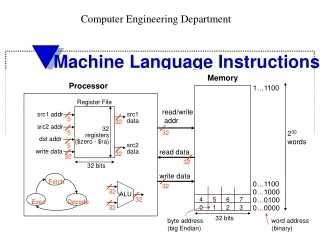
Abstract design Software Human abstract interface Thought hierarchy Chapters 9, 12 H.L. Language & abstract interface Operating Sys. VM Translator Virtual abstract interface Compiler Machine Chapters 7 - 8 Assembly Chapters 10 - 11 Language Assembler Chapter 6 abstract interface Computer Architecture Machine abstract interface Language Chapters 4 - 5 Gate Logic Hardware abstract interface Platform Chapters 1 - 3 Electrical Engineering Chips & Hardware Physics Logic Gates hierarchy Where we are at:
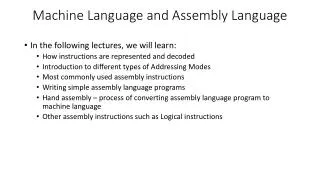
Machine language Abstraction – implementation duality: • Machine language ( = instruction set) can be viewed as a programmer-oriented abstraction of the hardware platform • The hardware platform can be viewed as a physical means for realizing the machine language abstraction Another duality: • Binary version • Symbolic version Loose definition: • Machine language = an agreed-upon formalism for manipulating a memory using a processor and a set of registers • Same spirit but different syntax across different hardware platforms.
1010 0001 0010 1011 ADD R1, R2, R3 Jacquard loom (1801) Augusta Ada King,Countess of Lovelace (1815-1852) Binary and symbolic notation Evolution: • Physical coding • Symbolic documentation • Symbolic coding • Translation and execution • Requires a translator.
Lecture plan • Machine languages at a glance • The Hack machine language: • Symbolic version • Binary version • Perspective (The assembler will be covered in lecture 6).
Typical machine language commands (a small sample) // In what follows R1,R2,R3 are registers, PC is program counter, // and addr is some value. ADD R1,R2,R3 // R1 R2 + R3 ADDI R1,R2,addr // R1 R2 + addr AND R1,R1,R2 // R1 R1 and R2 (bit-wise) JMP addr // PC addr JEQ R1,R2,addr // IF R1 == R2 THEN PC addr ELSE PC++ LOAD R1, addr // R1 RAM[addr] STORE R1, addr // RAM[addr] R1 NOP // Do nothing // Etc. – some 50-300 command variants
The Hack computer A 16-bit machine consisting of the following elements: Data memory:RAM – an addressable sequence of registers Instruction memory:ROM – an addressable sequence of registers Registers:D, A, M, where M stands for RAM[A] Processing:ALU, capable of computing various functions Program counter:PC, holding an address Control: The ROM is loaded with a sequence of 16-bit instructions, one per memory location, beginning at address 0. Fetch-execute cycle: later Instruction set: Two instructions: A-instruction, C-instruction.
@value // A value Where value is either a number ora symbol referring to some number. Coding example: @17 // A = 17 D = A // D = 17 The A-instruction Used for: • Entering a constant value( A = value) • Selecting a RAM location( register = RAM[A]) @17 // A = 17 D = M // D = RAM[17] Later @17 // A = 17 JMP // fetch the instruction // stored in ROM[17] • Selecting a ROM location( PC = A )
The C-instruction (first approximation) x = {A, D, M} y = {A, D, M, 1} dest = {A, D, M, MD, A, AM, AD, AMD, null} dest = x + y dest = x - y dest = x dest = 0 dest = 1 dest = -1 Exercise: Implement the following tasksusing Hack commands: • SetDtoA-1 • Set bothAandDtoA + 1 • SetDto19 • Set bothAandDtoA + D • SetRAM[5034]toD - 1 • SetRAM[53]to171 • Add 1 toRAM[7],and store the result inD.
Symbol table: j 3012 sum 4500 q 3812 arr 20561 (All symbols and values are arbitrary examples) The C-instruction (first approximation) Exercise: Implement the following tasksusing Hack commands: • sum = 0 • j = j + 1 • q = sum + 12 – j • arr[3] = -1 • arr[j] = 0 • arr[j] = 17 • etc. x = {A, D, M} y = {A, D, M, 1} dest = {A, D, M, MD, A, AM, AD, AMD, null} dest = x + y dest = x - y dest = x dest = 0 dest = 1 dest = -1
Control (focus on the yellow chips only) D D register a-bit ALU A A register A/M Mux RAM (selected register) M addressinput In the Hack architecture: • ROM = instruction memory • Program = sequence of 16-bit numbers, starting atROM[0] • Current instruction = ROM[PC] • To select instruction n from the ROM, we set A to n, using the instruction @n addressinput ROM (selected register) Instruction PC
Symbol table: sum 2200 x 4000 i 6151 END 50 NEXT 120 (All symbols and values in are arbitrary examples) Coding examples (practice) Hack commands: A-command:@value// set A to value C-command: dest = comp ; jump // dest = and ;jump // are optional Where: comp = 0 , 1 , -1 , D , A , !D , !A , -D , -A , D+1 ,A+1 , D-1, A-1 , D+A , D-A , A-D , D&A ,D|A , M , !M , -M ,M+1, M-1 , D+M , D-M ,M-D , D&M , D|M dest = M , D , MD , A , AM , AD , AMD, or null jump = JGT , JEQ , JGE , JLT , JNE , JLE , JMP, or null In the command dest = comp; jump, the jump materialzes if (comp jump 0) is true. For example, in D=D+1,JLT, we jump if D+1 < 0. Exercise: Implement the following tasks using Hack commands: • goto 50 • if D==0 goto 112 • if D<9 goto 507 • if RAM[12] > 0 goto 50 • if sum>0 goto END • if x[i]<=0 goto NEXT. Hack convention: • True is represented by -1 • False is represented by 0
High level: Hack: D not condition @IF_TRUE D;JEQ code block 2 @END 0;JMP (IF_TRUE) code block 1 (END) code block 3 if condition { code block 1} else { code block 2} code block 3 IF logic – Hack style Hack convention: • True is represented by -1 • False is represented by 0
Hack: High level: (LOOP) D not condition) @END D;JEQ code block 1 @LOOP 0;JMP (END) code block 2 while condition { code block 1 } Code block 2 WHILE logic – Hack style Hack convention: • True is represented by -1 • False is represented by 0
Side note (focus on the yellow chip parts only) D D register a-bit ALU A A register A/M Mux RAM (selected register) M addressinput • In the Hack architecture, the A register addresses both the RAM and the ROM, simultaneously. Therefore: • Command pairs like @addrfollowed by D=M;someJumpDirective make no sense • Best practice: in well-written Hack programs, a C-instruction should contain • either a reference to M, or • a jump directive, • but not both. addressinput ROM (selected register) Instruction PC
C language code: // Adds 1+...+100. into i = 1; into sum = 0; while (i <= 100){ sum += i; i++; } Complete program example Hack assembly code: // Adds 1+...+100. @i // i refers to some RAM location M=1 // i=1 @sum // sum refers to some RAM location M=0 // sum=0 (LOOP) @i D=M // D = i @100 D=D-A // D = i - 100 @END D;JGT // If (i-100) > 0 goto END @i D=M // D = i @sum M=D+M // sum += i @i M=M+1 // i++ @LOOP 0;JMP // Got LOOP (END) @END 0;JMP // Infinite loop Hack assembly convention: • Variables: lower-case • Labels: upper-case • Commands: upper-case Demo CPU emulator
Symbols in Hack assembly programs Symbols created by Hack programmers and code generators: Label symbols: Used to label destinations of goto commands. Declared by the pseudo command (XXX). This directive defines the symbol XXX to refer to the instruction memory location holding the next command in the program (within the program, XXX is called “label”) Variable symbols: Any user-defined symbol xxx appearing in an assembly program that is not defined elsewhere using the (xxx) directive is treated as a variable, and is “automatically” assigned a unique RAM address, starting at RAM address 16 By convention, Hack programmers use lower-case and upper-case letters for variable names and labels, respectively. Predefined symbols: I/O pointers: The symbols SCREEN and KBD are “automatically” predefined to refer to RAM addresses 16384 and 24576, respectively (base addresses of the Hack platform’s screen and keyboard memory maps) Virtual registers: covered in future lectures. VM control registers: covered in future lectures. // Typical symbolic // Hack code, meaning // not important @R0 D=M @INFINITE_LOOP D;JLE @counter M=D @SCREEN D=A @addr M=D (LOOP) @addr A=M M=-1 @addr D=M @32 D=D+A @addr M=D @counter MD=M-1 @LOOP D;JGT (INFINITE_LOOP) @INFINITE_LOOP 0;JMP Q: Who does all the “automatic” assignments of symbols to RAM addresses? A: The assembler, which is the program that translates symbolic Hackprograms into binary Hack program. As part of the translation process, the symbols are resolved to RAM addresses. (more about this in future lectures)
Perspective • Hack is a simple machine language • User friendly syntax: D=D+A instead of ADD D,D,A • Hack is a “½-address machine”: any operation that needs to operate on the RAM must be specified using two commands: an A-command to address the RAM, and a subsequent C-command to operate on it • A Macro-language can be easily developed • A Hack assembler is needed and will be discusses and developed later in the course.