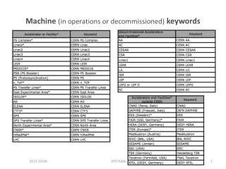
Introduction to RISC Architecture and Machine Instructions
This presentation covers the fundamentals of Reduced Instruction Set Computing (RISC) architecture, highlighting its simple instruction formats, limited operations, and high-speed execution advantages over Complex Instruction Set Computing (CISC). It explains the instruction formats similar to PowerPC and SUN Sparc processors, key features of the processor, and specific data transfer, arithmetic, logical, and shift instructions. The content focuses on how these machine instructions are structured and provide practical examples, making it a valuable resource for understanding RISC systems.

Introduction to RISC Architecture and Machine Instructions
E N D
Presentation Transcript
Machine InstructionsOperations ITCS 3181 Logic and Computer Systems 2014 B. Wilkinson Slides4-1.ppt Modification date: March 20, 2014
Instructions • We will use a simple instruction formats of a so-called reduced instruction set computer (RISC), which has the characteristics: • Simple, fixed length instruction format • A few addressing modes • Limited number of operations • Designed to achieve high speed of execution • It was recognized in the 1980’s that such processors would actually execute programs faster that the prevalent CISCs (complex instruction set computers).
Instruction format Our instruction format is quite similar to the G4/G5 PowerPC and SUN Sparc processors and also similar but not identical to that used in the assembly language simulator in the labs. Intel 64/IA32 processor family -- uses a very complex and archaic instruction format, based upon the early 8086 processor (which was themselves loosely based upon even earlier Intel processors). However Intel processors now convert this complex instruction format (CISC) internally to simpler RISC formats for performance reasons.
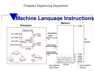
Some Key Features of Processor Used Thirty-two 32-bit integer registers called R0 to R31 2. One register, R0, holds zero permanently 3 All arithmetic done only between registers: - Three-register format op-code, destination register, source register 1, source register 2 or - Immediate addressing op-code destination, source register, constant 4. Memory operations limited to: load register, and store register using register indirect addressing plus offset only. R31 R30 R29 R28 R4 R3 R2 0000 … 0000 R1 R0 R31 holds return address for procedures. R29 is a stack pointer see later.
Data Transfer Instructions that copy the contents of one location to another location. Examples MOV R1,R2 ;R1 = R2 LD R3,100[R2] ;Contents of memory whose address is ;given by 100 + R2 copied to R3. ST [R5],R4 ;Contents of R4 copied to memory loc. ;whose address held in R5. (Offset = 0) Note LD and ST cause 32-bit transfers. Use LB and SB to cause 8-bit transfers. Instruction Comments
Arithmetic Instructions Performs an arithmetic operation such as addition, subtraction, multiplication or division. Examples ADD R1,R2,R3 ;R1 = R2 + R3 SUB R5,R4,3 ;R5 = R4 – 3 For literals (immediate addressing) Differences in assembly language notation. SUB R5,R4,3 ;R5 = R4 - 3 might be written as: SUB R5,R4,#3 ;R5 = R4 - 3 or SBI R5,R4,3 ;R5 = R4 - 3 depending upon assembly language.
Logical Instructions Performs bit-wise logical operation such as AND, OR, exclusive-OR, or NOT. AND, OR, exclusive-OR operate upon pairs of bits of two operands. Bit-wise AND, OR, Ex-OR, and NOT are available in C and Java (although you probably did not come across them!): C/Java Language Examples y = y & 1 ;bit-wise AND y with the number 1 z = z | 2 ;bit-wise OR z with the number 2
Machine Instruction Examples AND R1,R2,R3 ;R1 = R2 “AND” R3 if R2 = 10100010100101011000010100001111 R3 = 01011011111010100010100010111010 then R1 = 00000010100000000000000000001010 OR R1,R2,R3 ;R1 = R2 “OR” R3 if R2 = 10100010100101011000010100001111 R3 = 01011011111010100010100010111010 then R1 = 11111011111111111010110110111111
Shift Instructions Moves the bits of a location one or more places left or right. Again available in C/Java (although you probably did not come across them!): C/Java language Examples y = y << 1 ;shift y 1 place left 1 z = z >> 2 ;shift z 2 places right
Machine Instruction Examples Examples SHL R1,R1,1 ;Shift R1 left one place SHR R1,R1,1 ;Shift R1 right one place X = 0 or 1 see next slide
Arithmetical and Logical Shifts Two types of shift usually provided: “Logical” shift (SHL, SHR) Fill free end with 0, i.e. X = 0. “Arithmetic” shift (SAL, SAR) Arithmetic shifts multiple/divide by 2. Arithmetic shift right maintains value of sign bit, i.e. X= value of original sign bit.
Example Starting with a number 9 000 ... 0001001 Shift arithmetic left one place. Get 18 000 ... 0010010 Shift arithmetic right two places. Get 4 000 ... 0000100 i.e. lost the 0.5.
Question What is the difference, if any, between arithmetic shift left and logical shift left, i.e. what is the difference, if any, between: SHL R1, R1, 1 and SAL R1, R1, 1 Answer
Arithmetic shift left same as logical shift left (except arithmetic overflow may be detected). Note: Java has logical shift right - called unsigned right shift, >>>. Example x = x >>> 2;
Question What is the effect of the sequence? SAL R1, R1, 1 SAR R1, R1, 1 Answer
Rotate Instructions Moves bits of location one or more places left of right in a circular fashion. Examples ROL R1,R1,1 ;Rotate R1 left one place ROR R1,R1,1 ;Rotate R1 right one place Version of rotate exists where the rotate passes thro a Carry flag within the condition code register, see later about the CCR
Control Flow Compilers must translate statements such as: if ((x != y) && (z < 0)) { a = b + 5; b = b + 1; } into machine instructions. Unreasonable to try to provide a unique machine instruction for this IF statement because of the vast number of possible IF statements. Need to extract essential primitive operations for machine instructions.
Decompose into simple IF statements of the form: if (x relation y) goto L1; where: relation is any of usual relations allowed in high level languages (<, >, >=, <=, ==, !=) L1 is a label prefixed to an instruction to identify it.
i.e. translate if ((x != y) && (z < 0)) { a = b + 5; b = b + 1; } ... into if (x == y) goto L1; if (z >= 0) goto L1; a = b + 5; b = b + 1; L1: ... Label
There is several ways of implementing the IF statement. if (x relation y) goto L1; Here we will consider two ways: 1. Using one branch instruction. 2 Using two instructions, one to determine whether relationship is true, and another to branch to L1 if true.
1. Using one branch instruction Single “branch” machine instruction compares two registers and goes to the labeled location if the condition is true, i.e. Bcond Rs1, Rs2, L1 changes the execution sequence to the instruction labeled L1if Rs1 cond Rs2 is true, where condcan be any of six possible conditions, and Rs1andRs2can be any of the 32 registers.
Conditional Branch Instruction op-codes Bcond BcondCondition High level language notation BLBranch if less than < BGBranch if greater than > BGEBranch if greater or equal to >= BLEBranch if less or equal to <= BEBranch if equal == BNEBranch if not equal !=
Example To implement if (x == y) goto L1; . . . L1: by a single machine instruction, we get: BE R1,R2,L1 . . . L1: where the compiler allocates R1for xandR2fory.
Machine Instruction Encoding The instruction Bcond Rs1,Rs2,L1 requires an op-code (Bcond), the two source registers Rs1and Rs2, and L1to be specified. Note: Bcond is either BL, BG, BGE, BLE, or BNE
Specifying “target” location L1 Several ways L1 could be specified in instruction: Absolute (direct) addressing The address of L1held in instruction. (PC) Relative addressing The distance from branch instruction to labeled instruction stored in instruction. Program counter, see later
Absolute (direct) addressing BE R1,R2,120 . . . L1: ;location 120 say Note: Absolute addressing will not used in our design.
(PC) Relative Addressing BE R1,R2,+30 ;location 90 say . . . L1: ;location 120 say Offset/displacement Actual number in instruction may be different, see later.
Question How would one code: if (x > y) x = 10; with machine instructions where xand yare stored in R2and R3respectively? Answer
2. Condition Code Register Approach In this approach, we determine whether the Boolean condition in if (x relation y) goto L1; is true by subtracting y from xand recognizing whether the result is positive or negative, zero, or not zero: relationx - y < negative > positive and not zero >= positive or zero <= negative or zero == zero != not zero
Condition Code Register (CCR) Contains a set of flags (single bits) used to be able to recognize the different possible relationships (<, >, >=, <=, ==, !=) after the previous arithmetic operation. E.g. negative/positive flag and zero/not zero flag. Flags in condition code register indicate a particular aspect of the result of the last arithmetic instruction, i.e. positive or negative, zero or not zero, … Usually a form of subtract operation is first performed, although technically other arithmetic and logical operations can affect the condition code register.
Sign Flag (S or N flag) (positive or negative) Indicates whether previous arithmetic result is negative or positive. S = 1 for negative result S = 0for positive result. S is actually the most significant (sign) bit of the result of the previous arithmetic operation
Zero Flag Zero flag, Z: Z = 1 for result = 0 Z = 0 for result != 0 (Note zero is a positive number.)
Condition Code Register Condition Code register normally closely linked to the ALU (Arithmetic and Logic Unit):
Using Condition Code Register Decompose IF statement such as: if (x relation y) goto L1 into two sequential operations: Subtract yfrom xwhich sets condition code register according to result 2. Read condition code register and “branch” to L1 if specific condition indicated
Step 1 Subtract and Set Condition Code Register All arithmetic instructions set condition code register according to the result of the arithmetic operation, but a compare instruction is specifically provided, which is similar to a subtract instruction except the result is not stored anywhere, only the CCR flags are set according to the result. Example CMP R1, R2 ;R1 - R2, sets CCR flags
Step 2 Reading Condition Code Register and Branching A conditional branch instruction used to examine the values stored in the condition code register to determine whether the specific condition exists and to branch if it does. All six conditions usually available: BLBranch if less than BGBranch if greater than BGEBranch if greater or equal to BLEBranch if less or equal to BE (or BZ) Branch if equal BNE (or BNZ) Branch if not equal
Example Suppose x held in R1 and y held in R2. The if statement: if (x == y) goto L1; could be implemented by sequence of two instructions, CMPand BE: CMP R1,R2 ;Compare contents of R1, R2 (x, y) BE L1 ;Go to L1 if equal L1:
Example Suppose x held in R1 and y held in R2. The if statement: if (x == y) goto L1; could be implemented by sequence of two instructions, CMPandBE: CMP R1,R2 ;Compare contents of R1, R2 (x, y) BE L1 ;Go to L1 if equal L1:
Example Suppose x held in R1 and y held in R2. The if statement: if (x == y) goto L1; could be implemented by sequence of two instructions, CMPand BE: CMP R1,R2 ;Compare contents of R1, R2 (x, y) BE L1 ;Go to L1 if equal L1:
Another Example The if statement: if (x < y) goto L1; could be implemented by: CMP R1,R2 ;Compare contents of R1, R2 (x, y) BL L1 ;Go to L1 if x less than y L1:
Question A processor uses a condition code register approach for branch instructions. Write an assembly language sequence for the C/Java code: if ((a < b) && (a > 0)) b = a; assuming that the variables aandbare assigned to registers R1and R2respectively. Provide comments Use any reasonable hypothetical instructions. (Note && is the symbol for the logical AND operation.)
More complex constructions if - then - else Suppose we had to implement: if (a < b) c = a; else a = c; ... assuming that the variables a, b, and c are assigned to registers R1, R2, and R3 respectively.
Leads to: CMP R1,R2 ;Compare R1, R2 (x, y) BL L1 ;Go to L1 if a less than b MOV R1, R3 ;a = c L1: MOV R3,R1 ; c = a; L2: ... We need to alter the instruction sequence unconditionally. With the instructions we know about so far, it could be done with: CMP R1, R1 BE L2 ;if (x == x) goto L2; but there is a special instruction called a jump instruction to do it. Skip over c = a
JUMP Instructions Causes an unconditional change of execution sequence to a new location. Necessary to implement more complicated IF constructs, FOR, and WHILE loops. Using J as the opcode mnemonic, the jump instruction is: J L1 ;goto to L1
With jump instruction: CMP R1,R2 ;Compare R1, R2 (x, y) BL L1 ;Go to L1 if a less than b MOV R1, R3 ;a = c J L2 L1: MOV R3,R1 ;c = a; L2: ... Go to L2
For loops Suppose we had to implement the C/Java code sequence: for (i = 1; i < 10; i++) a = a * i; ... Let us assume iis held in register R1, and x is held in register R2. Possible solution MOV R1, 1 ;i = 1 L2: CMP R1,10 ;Compare R1 with 10 BGE L1 ;Go to L1 if end of loop MUL R2,R2,R1 ;a = a * i ADD R1,R1,1 ;increment i J L2 L1: ...
Mostly, conditional branch instructions used to implement small changes in sequences or program loops of relatively short length, so distance from branch/jump to target (label) quite small (compared to full address of the labeled instruction). Also good programming practice to limit sequence changes to short distance from current location to avoid difficult to read code. Relative addressing Specify target location as number of instructions from branch/jump instruction. Also makes code relocatable. (i.e. code can be loaded anywhere in memory without altering branch/jump instructions.)
Program Counter (PC) A register within the processor that holds the address of the next instruction to execute. PC-Relative Addressing The number of locations to the target is held in the instruction as an offset. Offset is added to the program counter to obtain the effective address.
Program Counter Details Let’s assume all instructions are 32 bits (four bytes) and each addressable memory location is one byte. PC hold address of instruction to be fetched from memory. After the instruction fetched, PC incremented by 4 before executing instruction.