Chapter 22 MACHINING OPERATIONS AND MACHINE TOOLS
Chapter 22 MACHINING OPERATIONS AND MACHINE TOOLS. Turning and Related Operations Drilling and Related Operations Milling Machining Centers and Turning Centers Other Machining Operations High Speed Machining. Machining.

Chapter 22 MACHINING OPERATIONS AND MACHINE TOOLS
E N D
Presentation Transcript
Chapter 22MACHINING OPERATIONS AND MACHINE TOOLS • Turning and Related Operations • Drilling and Related Operations • Milling • Machining Centers and Turning Centers • Other Machining Operations • High Speed Machining ISE 316 - Manufacturing Processes Engineering
Machining A material removal process in which a sharp cutting tool is used to mechanically cut away material so that the desired part geometry remains • Most common application: to shape metal parts • Machining is the most versatile and accurate of all manufacturing processes in its capability to produce a diversity of part geometries and geometric features • Casting can also produce a variety of shapes, but it lacks the precision and accuracy of machining ISE 316 - Manufacturing Processes Engineering
Classification of Machined Parts • Rotational - cylindrical or disk‑like shape • Nonrotational (also called prismatic) - block‑like or plate‑like Figure 22.1 ‑ Machined parts are classified as: (a) rotational, or (b) nonrotational, shown here by block and flat parts ISE 316 - Manufacturing Processes Engineering
Machining Operations and Part Geometry Each machining operation produces a characteristic part geometry due to two factors: • Relative motions between the tool and the workpart • Generating – part geometry is determined by the feed trajectory of the cutting tool • Shape of the cutting tool • Forming – part geometry is created by the shape of the cutting tool ISE 316 - Manufacturing Processes Engineering
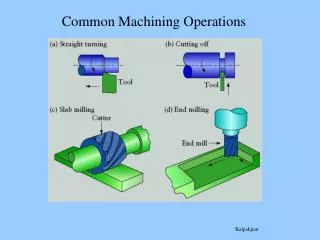
Figure 22.2 ‑ Generating shape: (a) straight turning, (b) taper turning, (c) contour turning, (d) plain milling, (e) profile milling ISE 316 - Manufacturing Processes Engineering
Figure 22.3 ‑ Forming to create shape: (a) form turning, (b) drilling, and (c) broaching ISE 316 - Manufacturing Processes Engineering
Figure 22.4 ‑ Combination of forming and generating to create shape: (a) thread cutting on a lathe, and (b) slot milling (old:Fig.25.41) ISE 316 - Manufacturing Processes Engineering
Turning A single point cutting tool removes material from a rotating workpiece to generate a cylindrical shape • Performed on a machine tool called a lathe • Variations of turning that are performed on a lathe: • Facing • Contour turning • Chamfering • Cutoff • Threading ISE 316 - Manufacturing Processes Engineering
Figure 22.5 ‑ Turning operation ISE 316 - Manufacturing Processes Engineering
Facing Tool is fed radially inward Figure 22.6 (a) facing ISE 316 - Manufacturing Processes Engineering
Contour Turning Instead of feeding the tool parallel to the axis of rotation, tool follows a contour that is other than straight, thus creating a contoured form Figure 22.6 (c) contour turning ISE 316 - Manufacturing Processes Engineering
Chamfering Cutting edge cuts an angle on the corner of the cylinder, forming a "chamfer" Figure 22.6 (e) chamfering ISE 316 - Manufacturing Processes Engineering
Cutoff Tool is fed radially into rotating work at some location to cut off end of part Figure 22.6 (f) cutoff ISE 316 - Manufacturing Processes Engineering
Threading Pointed form tool is fed linearly across surface of rotating workpart parallel to axis of rotation at a large feed rate, thus creating threads Figure 22.6 (g) threading ISE 316 - Manufacturing Processes Engineering
Figure 22.7 Diagram of an engine lathe, showing its principal components ISE 316 - Manufacturing Processes Engineering
Methods of Holding the Work in a Lathe • Holding the work between centers • Chuck • Collet • Face plate ISE 316 - Manufacturing Processes Engineering
Holding the Work Between Centers Figure 22.8 (a) mounting the work between centers using a "dog” ISE 316 - Manufacturing Processes Engineering
Chuck Figure 22.8 (b) three‑jaw chuck ISE 316 - Manufacturing Processes Engineering
Collet Figure 22.8 (c) collet ISE 316 - Manufacturing Processes Engineering
Face Plate Figure 22.8 (d) face plate for non‑cylindrical workparts ISE 316 - Manufacturing Processes Engineering
Turret Lathe Tailstock replaced by “turret” that holds up to six tools • Tools rapidly brought into action by indexing the turret • Tool post replaced by four‑sided turret to index four tools • Applications: high production work that requires a sequence of cuts on the part ISE 316 - Manufacturing Processes Engineering
Chucking Machine • Uses chuck in its spindle to hold workpart • Parts cannot be mounted between centers • Cutting tool actions controlled automatically • Operator’s job: to load and unload parts • Applications: short, light‑weight parts ISE 316 - Manufacturing Processes Engineering
Bar Machine • Similar to chucking machine except collet replaces chuck, permitting long bar stock to be fed through headstock • At the end of the machining cycle, a cutoff operation separates the new part • Highly automated (the term automatic bar machine is often used) • Applications: high production of rotational parts ISE 316 - Manufacturing Processes Engineering
Automatic Screw Machine • Same as automatic bar machine but smaller • Applications: high production of screws and similar small hardware items; hence, its name ISE 316 - Manufacturing Processes Engineering
Multiple Spindle Bar Machines • More than one spindle, so multiple parts machined simultaneously by multiple tools • Example: six spindle automatic bar machine works on six parts at a time • After each machining cycle, spindles (including collets and workbars) are indexed (rotated) to next position ISE 316 - Manufacturing Processes Engineering
NEW NCs or CNCs • high speed spindle (> 40,000 rpm) • high feed rate drive ( > 600 ipm) • high precision ( < 0.0001" accuracy)
Figure 22.9 ‑ (a) Part produced on a six‑spindle automatic bar machine; and (b) sequence of operations to produce the part: (1) feed stock to stop, (2) turn main diameter, (3) form second diameter and spotface, (4) drill, (5) chamfer, and (6) cutoff ISE 316 - Manufacturing Processes Engineering
Boring • Difference between boring and turning: • Boring is performed on the inside diameter of an existing hole • Turning is performed on the outside diameter of an existing cylinder • In effect, boring is an internal turning operation • Boring machines • Horizontal or vertical - refers to the orientation of the axis of rotation of machine spindle ISE 316 - Manufacturing Processes Engineering
Figure 22.12 ‑ A vertical boring mill –for large, heavy workparts ISE 316 - Manufacturing Processes Engineering
Drilling • Creates a round hole in a workpart • Contrasts with boring which can only enlarge an existing hole • Cutting tool called a drill or drill bit • Customarily performed on a drill press Figure 21.3 (b) drilling ISE 316 - Manufacturing Processes Engineering
Through Holes vs. Blind Holes Through‑holes - drill exits the opposite side of work Blind‑holes – drill does not exit work on opposite side Figure 22.13 ‑ Two hole types: (a) through‑hole, and (b) blind hole ISE 316 - Manufacturing Processes Engineering
Reaming Used to slightly enlarge a hole, provide better tolerance on diameter, and improve surface finish • Figure 22.14 ‑ • Machining operations related to drilling: • Reaming ISE 316 - Manufacturing Processes Engineering
Tapping Used to provide internal screw threads on an existing hole Tool called a tap Figure 22.14 (b) tapping ISE 316 - Manufacturing Processes Engineering
Counterboring Provides a stepped hole, in which a larger diameter follows a smaller diameter partially into the hole Figure 22.14 (c) counterboring ISE 316 - Manufacturing Processes Engineering
Upright Drill Stands on the floor Bench Drill Similar but smaller and mounted on a table or bench Figure 22.15 ‑ Upright drill press ISE 316 - Manufacturing Processes Engineering
Radial Drill Large drill press designed for large parts Figure 22.16 ‑ Radial drill press (Willis Machinery and Tools) ISE 316 - Manufacturing Processes Engineering
Work Holding for Drill Presses • Workpart can be clamped in a vise, fixture, or jig • Vise - general purpose workholder with two jaws • Fixture - workholding device that is usually custom‑designed for the particular workpart • Drill jig – similar to fixture but also provides a means of guiding the tool during drilling ISE 316 - Manufacturing Processes Engineering
Milling Machining operation in which work is fed past a rotating tool with multiple cutting edges • Axis of tool rotation is perpendicular to feed direction • Creates a planar surface; other geometries possible either by cutter path or shape • Other factors and terms: • Milling is an interrupted cutting operation • Cutting tool called a milling cutter, cutting edges called "teeth" • Machine tool called a milling machine ISE 316 - Manufacturing Processes Engineering
Figure 21.3 ‑ Two forms of milling: • peripheral milling, and (b) face milling ISE 316 - Manufacturing Processes Engineering
Peripheral Milling vs. Face Milling • Peripheral milling • Cutter axis is parallel to surface being machined • Cutting edges on outside periphery of cutter • Face milling • Cutter axis is perpendicular to surface being milled • Cutting edges on both the end and outside periphery of the cutter ISE 316 - Manufacturing Processes Engineering
Slab Milling The basic form of peripheral milling in which the cutter width extends beyond the workpiece on both sides • Figure 22.18 • slab milling ISE 316 - Manufacturing Processes Engineering
Slotting • Width of cutter is less than workpiece width, creating a slot in the work Figure 22.18 (b) Slotting ISE 316 - Manufacturing Processes Engineering
Conventional Face Milling Cutter overhangs work on both sides Figure 22.20 (a) conventional face milling ISE 316 - Manufacturing Processes Engineering
End Milling Cutter diameter is less than work width, so a slot is cut into part Figure 22.20 ‑ (c) end milling ISE 316 - Manufacturing Processes Engineering
Profile Milling Form of end milling in which the outside periphery of a flat part is cut Figure 22.20 (d) profile milling ISE 316 - Manufacturing Processes Engineering
Pocket Milling Another form of end milling used to mill shallow pockets into flat parts Figure 22.20 (e) pocket milling ISE 316 - Manufacturing Processes Engineering
Surface Contouring Ball‑nose cutter is fed back and forth across the work along a curvilinear path at close intervals to create a three dimensional surface form Figure 22.20 (f) surface contouring ISE 316 - Manufacturing Processes Engineering
Figure 22.23 (a) horizontal knee-and-column milling machine ISE 316 - Manufacturing Processes Engineering
Figure 22.23 (b) vertical knee‑and‑column milling machine ISE 316 - Manufacturing Processes Engineering
Machining Centers Highly automated machine tool capable of performing multiple machining operations under CNC control in one setup with minimal human attention • Typical operations are milling and drilling • Three, four, or five axes • Other features: • Automatic tool‑changing • Pallet shuttles • Automatic workpart positioning ISE 316 - Manufacturing Processes Engineering