Download

1 / 107
1.08k likes | 1.3k Vues
Chapter 5 Enhanced Direct Memory Access (EDMA) DSK 1-day Workshop Student Guide TMS320C6000 Peripherals (207-289). Learning Objectives. The need for a DMA (EDMA). Terms and definitions (with examples). EDMA functionality, including: Transfer modes and synchronisation. EDMA interrupt.

E N D
Chapter 5 Enhanced Direct Memory Access (EDMA) DSK 1-day Workshop Student Guide TMS320C6000 Peripherals(207-289)
Learning Objectives • The need for a DMA (EDMA). • Terms and definitions (with examples). • EDMA functionality, including: • Transfer modes and synchronisation. • EDMA interrupt. • Quick DMA (QDMA). • Programming the EDMA, including: • Using the Chip Support Library (CSL). • Example “inout” program using Ping-Pong EDMA.
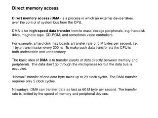
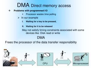
The Need for a DMA • There are two methods for transferring data from one part of the memory to another, these are using: (1) CPU. (2) DMA. • If a DMA is used then the CPU only needs to configure the DMA. Whilst the transfer is taking place the CPU is then free to perform other operations.
DAC How can we improve system performance? How can we Improve System? DSK HWI CPU McBSP CPU must: • Generate sine wave samples • Respond to McBSP interrupt • Send data to codec (via McBSP)
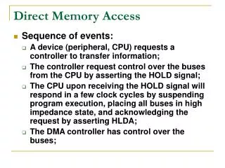
DAC Block Processing with EDMA DSK CPU Buffer McBSP EDMA CPU • Generates buffer of samples at a time EDMA • Handles McBSP interrupt, reduces CPU int. overhead • Sends data to codec If EDMA handles the McBSP event, how does the CPU know when to run?
DSK CPU Buffer McBSP0 EDMA DAC EDMAinterrupt 8KHz buffersize XEVT0event 8KHz Use EDMA • EDMA interrupt tells CPU when to run • Reduces CPU interrupts by factor of buffersize How does the EDMA work?
Introduction to the EDMA • The ‘C6416 on-chip EDMA controller allows data transfers between the level two (L2) cache memory controller and the device peripherals. • These transfers include: • Cache servicing. • Non-cacheable memory accesses. • User programmed data transfers. • Host accesses.
EDMA Interface • The C621x/C671x/C641x Block diagram. The EDMA allows data transfer to/from any addressable memory spaces.
EDMA Functionality • The data transfer is performed with zero overhead. • It is transparent to the CPU which means that the EDMA and CPU operations can be independent. • However, if the EDMA and CPU both try to access the same memory location arbitration will be performed by the program memory controller.
mem1 A0 A1 A2 A3 A4 A5 EDMA Options Source Destination Xfr Count EDMA Functionality Source Destination mem2 A0 A1 A0 A1 A2 A3 A4 A5 A2 A3 A4 A5 What information is needed by the EDMAto perform transfers?
EDMA • 16 channels • Stores parameters for 69 more transfer config’s • Per channel: high/low priority, else round-robin Channel 0 Channel 1 Channel 2 ... Options Source 15 Transfer Count Reload 1 Destination Reload 2 Index ... Count Reload† Link Addr† Reload 69 31 16 15 0 EDMA Overview
EDMA Overview EDMA Channel 0 Channel 1 Channel 2 ... Options Source 15 Transfer Count Reload 1 Destination Reload 2 Index ... Count Reload† Link Addr† Reload 69 31 16 15 0 QDMA Quick-DMA • Additional DMA channel • Higher priority • Less transfer overhead • No sync capability • Can’t autoinit (no † registers) Enhanced DMA • 16 channels • Stores parameters for 69 more transfer config’s • Per channel: high/low priority, else round-robin
EDMA Features • The ‘C6416 on-chip EDMA controller has the following features: • 16 channels. • 1 auxiliary channel dedicated for the HPI (not accessible to the user). • 1 Quick DMA (QDMA).
EDMA Channel Priorities • The ‘C6416 EDMA channels have two programmable levels of priority (Level 0 reserved only for the L2). Options (PRI 31:29) Priority Level Requestors 000b 001b 010b 011-111b Level 0: Urgent Level 1: High Level 2: Low Reserved L2 Controller * EDMA, QDMA, HPI EDMA, QDMA * Requests from CPU/L1 and L2 controller
EDMA Performance • The ‘C6211/C6711 EDMA can perform element transfers with single-cycle throughput provided there is no conflict. • The following conditions can limit the performance: • EDMA stalls when there are multiple transfer requests on the same priority level. • EDMA accesses to L2 SRAM with lower priority than the CPU.
Block Frame Element Frame 1 Elem 1 Frame 2 Elem 2 ESIZE .. .. Elem N Frame M 28 27 ESIZE Options Source Transfer Count Destination # Frames # Elements Index 31 16 15 0 Cnt Reload Link Addr 31 0 EDMA - How much to move The smallest piece of information transferred by the EDMA is called... 00: 32-bits 01: 16-bits 10: 8-bits 11: rsvd • N = Element count (ELECNT). • M = Frame count (FRMCNT). • See SPRU190page 6-5 for more.
How the EDMA Works Options Channel 0 Source Channel 1 Transfer Count ... Channel 15 Destination Reload 0 Index Reload 1 Count Reload Link Addr ... 31 16 15 0 Reload 69 • Reload channel parameters. • The EDMA has a parameter RAM composed of: • Channel parameters. Parameter RAM
Options Source Channel 0 Transfer Count Channel 1 Destination Channel 2 Index ... Count Reload Link Addr 15 31 16 15 0 Reload 1 Reload 2 ... Reload 69 EDMA: Linking Transfers • Offloads CPU ... can reinitialize EDMA all channel registers • Next transfer configuration specified by Link Address • Perform simple re-initialization or create linked-list of events • Useful for ping-pong buffers, data sorting, circular buffers, etc.
How the EDMA Works • The EDMA has a parameter RAM composed of: • Channel parameters. • Reload channel parameters. • The user programs both channel and reload channel parameters. • The channel parameters contain all the information needed for the EDMA in order to perform a transfer. • When a transfer is complete the channel parameters are reloaded from the corresponding reload channel.
EDMA Parameters Options Source Transfer Count Destination Index Count Reload Link Addr 31 16 15 0 • The parameters in the parameter table need to be determined before the EDMA can be programmed.
EDMA Parameters (Options) 31 29 28 27 26 25 24 23 22 21 20 19 16 15 2 1 0 PRI ESIZE 2DS SUM 2DD DUM TCINT TCC RSVD LINK FS EDMA Channel Options Register Bit Field 31:29 28:27 26 25:24 23 22:21 20 19:16 1 0 Label PRI ESIZE 2DS SUM 2DD DUM TCINT TCC LINK FS Description Priority levels for the EDMA event Element size (32/16/8-bit) Source dimension Source address update mode Destination dimension Destination address update mode Transfer complete interrupt enable Transfer complete code Link Frame synchronisation
EDMA Parameters • Source: Start address of the source. • Transfer Count: • Upper 16 bits [31:16]: Frame count. • Lower 16 bits [15:0]: Element count. • Destination: Start address of the destination.
EDMA Parameters • Index: • Upper 16 bits [31:16]: Frame index. • Lower 16 bits [15:0]: Element index. • Count reload: Value to be reloaded into the element count when a frame is complete (only used in 1-D mode). • Link address: Specifies the address from where the parameters are reloaded. The 16-bit value is added to 0x01A0 xxxx to form the 32-bit address.
EDMA Synchronization • Two methods for initiating a transfer: (1) CPU initiated. This is known as unsynchronized EDMA. With this method the CPU writes to the Event Register (ER) through the Event Set Register (ESR) in order to start the EDMA transfer (this can be used to simulate an event).
EDMA Synchronization • Two methods for initiating a transfer: (1) CPU initiated. (2) Event triggered. In this case the event is latched in the Event Register (ER) which then triggers the transfer. The events that can trigger a transfer are given on the following slide.
EDMA Synchronization - CPU initiated Sync event Event Register Event Enable Register Event Set Register 1 Start Channel 2 transfer Event Clear Register
EDMA Synchronization - Event triggered Sync event Enable Channel 2 1 Event Register 1 Event Enable Register Start Channel 2 transfer Event Set Register Event Clear Register
EDMA Synchronization - Event trigger Disable Sync event Disable Channel 2 0 Event Register 1 0 Event Enable Register No transfer Event Set Register Clear event bit Event Clear Register 1
EDMA Events Channel 0 1 2 3 4 5 6 7 8 9 10 11 12 13 14 15 Event DSPINT TINT0 TINT1 SD_INT EXT_INT4 EXT_INT5 EXT_INT6 EXT_INT7 EDMA_TCC8 EDMA_TCC9 EDMA_TCC10 EMDA_TCC11 XEVT0 REVT0 XEVT1 REVT1 Event Description Host port host to DSP interrupt Timer 0 interrupt Timer 1 interrupt EMIF SDRAM timer interrupt External interrupt pin 4 External interrupt pin 5 External interrupt pin 6 External interrupt pin 7 EDMA transfer complete code 1000b interrupt EDMA TCC 1001b interrupt EDMA TCC 1010b interrupt EDMA TCC 1011b interrupt McBSP0 transmit event McBSP0 receive event McBSP1 transmit event McBSP1 receive event • An event can be cleared using the CPU by writing to the Event Clear Register (ECR).
Transfer Synchronization 26 23 2DS 2DD Options Register Destination dimension Source dimension • 0b = 1 dimensional • 1b = 2 dimensional • The synchronization mode depends on whether or not the transfer is two dimensional. • Therefore first specify that the transfer is either 1-D or 2-D.
1-D Synchronisation • There are two modes of synchronisation in the 1-D transfer mode. • These are: • Element synchronized: each event causes one element to be transferred. • Frame synchronized: each event causes a whole frame to be transferred. • The FS bit is used to specify the synchronization mode.
1-D Transfer Synchronization 0 FS Options Register • Element synchronized (FS=0): • In this case the EDMA transfers each element after receiving the synchronization event until the whole frame is transferred. • The element count is then reloaded and the frame count decremented. • The frame index is then added to the last element address to calculate the next frame start address. • If the link is enabled (LINK=1b) then the transfer parameters are reloaded.
Example: 1-D Transfer with FS=0 8-bit Pixels 1 2 3 4 5 6 8 DST: 7 8 9 10 11 12 9 13 14 15 16 17 18 10 19 20 21 22 23 24 11 25 26 27 28 29 30 8 bits • 00b = 32-bits • 01b = 16-bits • 10b = 8-bits • 11b = Reserved • 00b = Fixed • 01b = Increment • 10b = Decrement • 11b = Modified by INDEX • FRMCNT = M - 1 Source Destination • ESIZE = 10b • ELECNT = 4 • FRMCNT = 0 • SUM = 01b SRC: 8 8 9 10 11 9 10 11 Sync event
Example: 1-D Transfer with FS=0 8-bit Pixels 1 2 3 4 5 6 8 7 8 8 9 9 10 10 11 11 12 9 13 14 15 16 17 18 10 19 20 21 22 23 24 11 25 26 27 28 29 30 Source Destination SRC: DST: 8 9 10 11 8 bits ESIZE 10 Options Source = SRC+7 FRMCNT = 0 ELECNT = 4 Destination = DST FRMIDX ELEIDX Count Reload Link Addr 31 16 15 0
Example: 1-D Transfer with FS=0 8-bit Pixels 1 2 3 4 6 DST: 5 6 7 8 10 9 10 11 12 14 13 14 15 16 18 17 18 19 20 22 21 22 23 24 25 26 27 28 8 bits In this mode: Next frame addr = Last element addr + FRMIDX Source Destination • ESIZE = 10b (8-bits) • ELECNT = 5, FRMCNT = 0 • SUM = 11b • ELEIDX = 4 SRC: 6 6 10 Sync event 10 14 14 18 18 22 22
1-D Transfer Synchronisation • Frame synchronized (FS=1): • In this case the EDMA transfers a whole frame after receiving the synchronization event. • In this mode the frame index no longer represents the difference between the address of the last element of the frame and the start address of the next frame. • The frame index is added to the start address of the frame to derive the start address of the next frame. • See the example on the following slide.
Example: 1-D Transfer with FS=1 16 24 18 26 20 28 16-bit Data 1 2 3 4 5 6 7 8 8 8 9 10 10 11 12 12 13 14 10 15 16 17 18 19 20 21 32 34 12 40 42 22 23 24 25 26 27 28 36 16 29 30 31 32 33 34 35 ... 8 16 40 36 37 38 39 40 41 42 36 42 ... 10 44 43 44 45 46 47 48 49 40 36 44 12 42 44 ... 16 bits Source Destination • All elements in a frame are offset by ELEIDX bytes. • All frames in a block are offset by FRMIDX bytes. SRC: DST: Sync event
Example: 1-D Transfer with FS=1 16 24 18 26 20 28 16-bit Data 1 2 3 4 5 6 7 8 8 8 9 10 10 11 12 12 13 14 10 15 16 17 18 19 20 21 32 34 12 40 42 22 23 24 25 26 27 28 16 29 30 31 32 33 34 35 ... 8 16 40 36 36 37 38 39 40 41 42 36 10 ... 42 44 43 44 45 46 47 48 49 40 36 12 44 42 44 16 bits In this mode: Next frame addr = First element addr + FRMIDX Source Destination • ESIZE = 01b (16bits) • ELECNT = 3 • FRMCNT = 4 • SUM = 11b, 2DS = 0, FS = 1 • FRMIDX = 16, ELEIDX = 4 SRC: DST:
Example: 1-D Transfer with FS=1 8-bit Pixels 1 2 3 4 5 6 7 8 9 10 11 12 Source Destination 13 14 15 16 17 18 19 20 21 22 23 24 25 26 27 28 29 30 SRC: 2 2 DST: 4 4 14 14 16 16 26 26 28 28 8 bits 26 14 2 28 16 4 Sync event • ESIZE = 10b • ELECNT = 2 • FRMCNT = 2 • SUM = 01b, 2DS =0b, FS = 1 • FRMIDX = 12, ELEIDX = 2
2-D Synchronization • There are two modes of synchronization in the 2-D transfer mode. • These are: • Array synchronized: each event causes one line of the array to be transferred. • Block synchronized: each event causes the entire block to be transferred. • The FS bit is used to specify the synchronization mode.
2-D Transfer Synchronization • Array synchronized (FS=0): • This is the same as the 1-D frame synchronisation mode except that the elements are all contiguous. • One array is transferred per synchronisation event. • The frame count is equal to the number of frames minus one because when the FRMCNT=0 the complete transfer parameters are reloaded after sending the last transfer request to the address generation hardware. • The frame index is added to the start address of the frame to derive the next frame address.
Example: 2-D Transfer with FS=0 16-bit Data 1 2 3 4 5 6 7 8 DST: 8 9 10 11 12 13 14 9 29 36 22 8 15 37 23 30 16 9 17 24 31 10 38 11 18 40 32 25 15 16 17 18 19 20 21 10 22 23 24 25 26 27 28 11 11 29 30 31 32 33 34 35 15 15 8 36 37 38 39 40 41 42 ... ... 9 43 44 45 46 47 48 49 40 40 10 16 bits Source Destination • With 2D transfers there is no indexing between elements, therefore ELEIDX is not used in 2D transfers. • To specify a 2D source set 2DS in channel options. SRC: Sync event
Example: 2-D Transfer with FS=0 16-bit Data 1 2 3 4 5 6 7 8 DST: 8 9 10 11 12 13 14 9 22 36 15 29 8 16 23 37 9 30 24 31 17 38 10 11 32 25 40 18 15 16 17 18 19 20 21 10 22 23 24 25 26 27 28 11 11 29 30 31 32 33 34 35 15 15 8 36 37 38 39 40 41 42 ... ... 9 43 44 45 46 47 48 49 40 40 10 16 bits In this mode: Next frame addr = First element addr + FRMIDX Source Destination SRC: • ESIZE = 01b (16bits) • ELECNT = 4, FRMCNT = 4 • SUM = 01b, 2DS = 1b • FRMIDX = 14, ELEIDX = N/A
2-D Transfer Synchronization • Block synchronized (FS=1): • This is the same as the 1-D frame synchronization mode except that the elements are all contiguous. • The entire block is transferred following the synchronization event. • At the end of each frame the frame index is added to the last element address to calculate the next frame start address.
Example: 2-D Transfer with FS=1 16-bit Data 1 2 3 4 5 6 7 8 DST: 8 9 10 11 12 13 14 9 22 8 36 15 29 16 9 37 23 30 38 17 24 10 31 25 18 32 40 11 15 16 17 18 19 20 21 10 22 23 24 25 26 27 28 11 11 29 30 31 32 33 34 35 15 15 8 36 37 38 39 40 41 42 ... ... 9 43 44 45 46 47 48 49 40 40 10 16 bits In this mode: Next frame addr = Last element addr + FRMIDX Source Destination SRC: Sync event • ESIZE = 01b (16bits) • ELECNT = 4, FRMCNT = 4 • SUM = 01b, 2DS = 1b • FRMIDX = 8, ELEIDX = N/A
EDMA Interrupt Generation • The EDMA controller is responsible for generating transfer completion interrupts to the CPU. • The EDMA generates a single interrupt (EDMA_INT) to the CPU on behalf of all 16 channels. • The programmer has to read the CIPR register to determine which channel caused the interrupt or which interrupts are pending while the ISR is being serviced.
EDMA Interrupt Generation 31 20 19 16 0 OPTIONS TCINT TCC • Each channel has an OPTIONS register • OPTIONS contains: • TCINT - do you want to interrupt CPU? • TCC - 4 bit completion code (your choice)
EDMA Interrupt Generation 31 31 15 20 14 19 8 16 7 6 5 4 3 2 1 0 0 CIPR OPTIONS rsvd CIP15 TCINT CIP14 TCC CIP8 CIP7 CIP6 CIP5 CIP4 CIP3 CIP2 CIP1 CIP0 • Each channel has an OPTIONS register • OPTIONS contains: • TCINT - do you want to interrupt CPU? • TCC - 4 bit completion code (your choice) • Upon completion: If you set TCINT = 1, then CIPR bit equal to TCC value (you set) is set to one