Download
1 / 101
1.01k likes | 1.06k Vues
Learn about ISDN (Integrated Services Digital Network), its advantages, disadvantages, standards, and access methods, including B channels and D channels. Discover ISDN's role in achieving worldwide connectivity and how it compares to traditional telephone services.

E N D
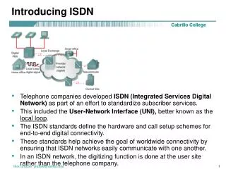
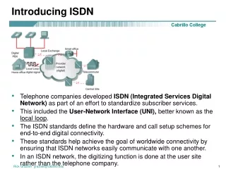
Introducing ISDN • Telephone companies developed ISDN (Integrated Services Digital Network) as part of an effort to standardize subscriber services. • This included the User-Network Interface (UNI), better known as the local loop. • The ISDN standards define the hardware and call setup schemes for end-to-end digital connectivity. • These standards help achieve the goal of worldwide connectivity by ensuring that ISDN networks easily communicate with one another. • In an ISDN network, the digitizing function is done at the user site rather than the telephone company. Rick Graziani graziani@cabrillo.edu
Introducing ISDN • Unlike POTS, ISDN is digital from end to end. • With asynchronous connections (POTS) the local loop is analog and requires PCM (Pulse Code Modulation) - explained later. • Benefits of ISDN include: • Carries a variety of user traffic signals, including data, voice, and video • Offers much faster call setup than modem connections • B channels provide a faster data transfer rate than modems • B channels are suitable for negotiated Point-to-Point Protocol (PPP) links Rick Graziani graziani@cabrillo.edu
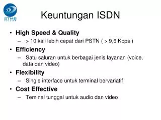
ISDN Advantages • ISDN also provides more bandwidth than a traditional 56 kbps dialup connection. • ISDN uses bearer channels, also called B channels, as clear data paths. • Each B channel provides 64 kbps of bandwidth. • An ISDN connection with two B channels would provide a total usable bandwidth of 128 kbps. • Each ISDN B channel can make a separate serial connection to any other site in the ISDN network. • ISDN lines can be used in conjunction with PPP encapsulation. Rick Graziani graziani@cabrillo.edu
ISDN Disadvantages • BRI is slower than DSL and cable • More expensive than DSL and cable • Bottom line: ISDN, in its current form, is no longer a “first-choice” technology. Rick Graziani graziani@cabrillo.edu
Why 64Kbps channels and what is PCM? CCNP: • This will be explained in a later presentation on T1. • For now, 64,000 bps is what’s required to carry a single phone call over a link (an analog call which has been digitized). • PCM (Pulse Code Modulation) is how the analog signal is translated to digital and visa versa. Rick Graziani graziani@cabrillo.edu
ISDN standards and access methods • ITU-T groups and organizes the ISDN protocols according to the following general topic areas: • E Protocols – Recommend telephone network standards for ISDN. For example, international addressing for ISDN. • I Protocols – Deal with concepts, terminology, and general methods. • Q Protocols – Cover how switching and signaling should operate. The term signaling in this context means the process of establishing an ISDN call. Short Term Memory Rick Graziani graziani@cabrillo.edu
ISDN standards and access methods ISDN standards define two main channel types • The bearer channel, or B channel, is defined as a clear digital path of 64 kbps • The second channel type is called a delta channel, or D channel. • There can either be 16 kbps for the Basic Rate Interface (BRI) or 64 kbps for the Primary Rate Interface (PRI). Rick Graziani graziani@cabrillo.edu
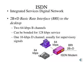
ISDN standards and access methods • ISDN is widely available in two flavors: • BRI: Basic Rate Interface • 2 64 Kbps Bearer Channels,16 Kbps Delta Channel (for control information), 48 Kbps for framing and synchronization • 2B + 1D (2B+D) • 192 Kbps = 128+16+48 • PRI: Primary Rate Interface • 23B + 1D (T1), the D channel is 64-kbps • 30B + 1D (E1), European E1 • 1.544 Mbps (North America) or 2.048 Mbps (E1) Rick Graziani graziani@cabrillo.edu
B Channels • The B channels can be used for relatively high-speed data transport. • In this mode, the information is carried in frame format, using either HDLC or PPP as the Layer 2 protocol. • PPP is more robust than HDLC because it provides a mechanism for authentication and negotiation of compatible link and protocol configuration. Rick Graziani graziani@cabrillo.edu
D Channel • When a TCP connection is established, there is an exchange of information called the connection setup. • This information is exchanged over the path on which the data will eventually be transmitted. • Both the control information and the data share the same pathway. • This is called in-band signaling. • ISDN however, uses a separate channel for control information, theD channel. • This is called out-of-band signaling. • The D channel carries signaling messages, such as call setup and teardown, to control calls on B channels. • Traffic over the D channel employs the Link Access Procedure on the D Channel (LAPD) protocol. • LAPD is a data link layer protocol based on HDLC. Rick Graziani graziani@cabrillo.edu
ISDN 3-layer model and protocols • ISDN utilizes a suite of ITU-T standards spanning the physical, data link, and network layers of the OSI reference model. • The ISDN BRI and PRI physical layer specifications are defined in ITU-T I.430 and I.431, respectively. • The ISDN data link specification is based on LAPD and is formally specified in the following, ITU-T Q.920, ITU-T Q.921, ITU-T Q.922, ITU-T Q.923 • The ISDN network layer is defined in ITU-T Q.930, also known as I.450 and ITU-T Q.931, also known as I.451. • These standards specify user-to-user, circuit-switched, and packet-switched connections. Short Term Memory Layer 3 Q.931 Layer 2 Q.921 I like the “older” chart. Rick Graziani graziani@cabrillo.edu
BRI Physical Layer • BRI service is provided over a local copper loop that traditionally carries analog phone service. • While there is only one physical path for a BRI, there are three separate information paths, 2B+D. • Information from the three channels is multiplexed into the one physical path. • ISDN physical layer, or Layer 1, frame formats differ depending on whether the frame is outbound or inbound. Rick Graziani graziani@cabrillo.edu
BRI Physical Layer • If the frame is outbound, it is sent from the terminal to the network. • Outbound frames use the TE frame format. • If the frame is inbound, it is sent from the network to the terminal. • Inbound frames use the NT frame format. Short Term Memory These Reference Points will be discussed in a moment, but this is where they get TE and NT from. Rick Graziani graziani@cabrillo.edu
BRI Physical Layer 4,000 frames per second • ISDN BRI frames contain 48 bits. • Four thousand of these frames are transmitted every second, 4,000 x 48 = 192,000 bps. • Each B channel, B1 and B2, have a capacity of 2(8*4000) = 64 kbps, 128 kbps for both B channels (B1 and B2) • The D channel has a capacity of 4*4000 = 16 kbps(D) • Framing and overhead 12*4,000 = 48,000 kbps. (F, L, E, A, S) 64k (16*4,000) - B1 channel 64k (16*4,000) - B2 channel 16k (4*4,000) - D channel 48k (12*4,000) – Framing/Overhead ------------------------------------------------ 192 kbps BRI Total 144 kbps = B1 + B2 + D (2B+D) B1, B2, D and Framing Bits Rick Graziani graziani@cabrillo.edu
BRI Physical Layer 4,000 frames per second The overhead bits of an ISDN physical layer frame are used as follows: • Framing bit – Provides synchronization • Load balancing bit – Adjusts the average bit value • Echo of previous D channel bits – Used for contention resolution when several terminals on a passive bus contend for a channel • Activation bit – Activates devices • Spare bit – Unassigned Short Term Memory Rick Graziani graziani@cabrillo.edu
ISDN Data Link Layer • The LAPD flag and control fields are identical to those of HDLC. • The LAPD address field is 2 bytes long. • Service access point identifier (SAPI), which identifies the portal at which LAPD services are provided to Layer 3. • The command/response bit (C/R),indicates whether the frame contains a command or a response. • The second byte contains the terminal endpoint identifier (TEI). • Each piece of terminal equipment on the customer premises needs a unique identifier. • The TEI may be statically assigned at installation, or the switch may dynamically assign it when the equipment is started up. • Statically assigned TEIs range from 0 to 63. • Dynamically assigned TEIs range from 64 to 126. • A TEI of 127, or all 1s, indicates a broadcast. Short Term Memory Rick Graziani graziani@cabrillo.edu
ISDN Data Link Layer • Where you see this information. Router#show isdn status Global ISDN Switchtype = basic-ni ISDN BRI0 interface dsl 0, interface ISDN Switchtype = basic-ni Layer 1 Status: ACTIVE Layer 2 Status: TEI = 64, Ces = 1, SAPI = 0, State = MULTIPLE_FRAME_ESTABLISHED TEI = 65, Ces = 2, SAPI = 0, State = MULTIPLE_FRAME_ESTABLISHED Spid Status: TEI 64, ces = 1, state = 5(init) spid1 configured, spid1 sent, spid1 valid TEI 65, ces = 2, state = 5(init) spid2 configured, spid2 sent, spid2 valid Layer 3 Status: 1 Active Layer 3 Call(s) Rick Graziani graziani@cabrillo.edu
Call Setup • To establish an ISDN call, the D channel is used between the router and the ISDN switch to control functions such as call setup, signaling, and termination. • Signal System 7 (SS7) signaling is used between the switches within the service provider network. • These functions are implemented in the Q.931 protocol. • The Q.931 standard recommends a network layer connection between the terminal endpoint and the local ISDN switch, but it does not impose an end-to-end recommendation. • Not an end-to-end function but processed by the switch. • Depending upon the switch type, you may or may not get all of the steps show above. Short Term Memory Rick Graziani graziani@cabrillo.edu
Call Setup – In detail • The following information discusses “some” of these steps. FYI Rick Graziani graziani@cabrillo.edu
Call Setup • The D channel is used to send the called number to the local ISDN switch. • The local switch uses the SS7 signaling protocol to set up a path and pass the called number to the remote ISDN switch. • The remote ISDN switch signals the destination over the D channel. FYI Rick Graziani graziani@cabrillo.edu
Call Setup • The destination ISDN NT-1 device sends the remote ISDN switch a call-connect message. • The remote ISDN switch uses SS7 to send a call-connect message to the local switch. • The local ISDN switch connects one B channel end-to-end, leaving the other B channel available for a new conversation or data transfer. Both B channels can be used simultaneously. FYI Rick Graziani graziani@cabrillo.edu
ISDN reference points Short Term Memory Rick Graziani graziani@cabrillo.edu
ISDN reference points Short Term Memory Rick Graziani graziani@cabrillo.edu
ISDN Interfaces • To connect devices that perform specific functions, the interface between the two devices needs to be well defined. • R – References the connection between a non-ISDN compatible device Terminal Equipment type 2 (TE2) and a Terminal Adapter (TA), for example an RS-232 serial interface. • S – References the points that connect into the customer switching device Network Termination type 2 (NT2) and enables calls between the various types of customer premises equipment. • T – Electrically identical to the S interface, it references the outbound connection from the NT2 to the ISDN network or Network Termination type 1 (NT1). • U – References the connection between the NT1 and the ISDN network owned by the telephone company. Short Term Memory Rick Graziani graziani@cabrillo.edu
ISDN reference points CAUTION: Some routers contain NT1’s. Never connect a router with a U interface into a NT1. It will most likely ruin the interface. Know what type of interface your router has! • Because the S and T references are electrically similar, some interfaces are labeled S/T interfaces. Although they perform different functions, the port is electrically the same and can be used for either function. Rick Graziani graziani@cabrillo.edu
Cisco Interfaces S/T interface requires an NT1 connection. • In the United States, the customer is required to provide the NT1. • In Europe and various other countries, the telephone company provides the NT1 function and presents an S/T interface to the customer. Rick Graziani graziani@cabrillo.edu
BRI S/T Interface – Cisco 2503 Rick Graziani graziani@cabrillo.edu
ISDN switch types • Routers must be configured to identify the type of switch with which they will communicate. • Available ISDN switch types vary, depending in part on the country in which the switch is being used. • As a consequence of various implementations of Q.931, the D channel signaling protocol used on ISDN switches varies from vendor to vendor. • Before the router can be connected to an ISDN service, it must be configured for the switch type used at the CO. • This information must be specified during router configuration. Rick Graziani graziani@cabrillo.edu
ISDN switch types Switch types used for router configuration. Rick Graziani graziani@cabrillo.edu
SPIDs • In addition to knowing the switch type the service provider is using, it may also be necessary to know what service profile identifiers (SPIDs) are assigned by the telco. • A SPID is a number provided by the ISDN carrier to identify the line configuration of the BRI service. • SPIDs allow multiple ISDN devices, such as voice and data equipment, to share the local loop. • SPIDs are required by DMS-100 and National ISDN-1 switches. • SPIDs are used only in North America and Japan. • In many cases when configuring a router, the SPIDs will need to be entered. Nortel DMS-100 Switch Rick Graziani graziani@cabrillo.edu
SPIDs • SPIDs are a series of characters that usually resemble telephone numbers. • SPIDs identify each B channel to the switch at the central office. • If SPIDs are necessary, but are not configured correctly, the initialization will fail, and the ISDN services cannot be used. Rick Graziani graziani@cabrillo.edu
Configuring ISDN – Switch Type • The command isdn switch-typeswitch-type can be configured at the global or interface command mode to specify the provider ISDN switch. • Configuring the isdn switch-type command in the global configuration mode sets the ISDN switch type identically for all ISDN interfaces. • Individual interfaces may be configured, after the global configuration command, to reflect an alternate switch type. Router(config)#isdn switch-typeswitch-type Router(config-if)#isdn switch-typeswitch-type Rick Graziani graziani@cabrillo.edu
Configuring ISDN interface Router(config)#interface bri number Router(config-if)# If the router is a TE2 device, which does not have a native BRI, it must use an external ISDN terminal adapter. On a TE2 router, configure the appropriate serial interface to send the ISDN traffic to the TA. Terminal Adapter Rick Graziani graziani@cabrillo.edu
Configuring ISDN – Encapsulation (Optional) • A method of datagram encapsulation is needed for data to be transported when dial-on-demand routing (DDR) or a user creates an end-to-end path over ISDN. • The most common Layer 2 encapsulation protocol is PPP. • Available encapsulations for ISDN include the following: • PPP • HDLC (default) • Frame Relay • LAPB • Combinet Proprietary Protocol (CPP) Router(config-if)#encapsulation [ppp | lapb | hdlc | x25 | cpp] Rick Graziani graziani@cabrillo.edu
Configuring ISDN – Optional SPIDs • DMS-100 and National ISDN-1 switches support only two SPIDs per BRI. • One SPID is supported for each B channel. • If both B channels will be used for data only, configure the router for both SPIDs, one for each B channel. • Data and voice cannot run over the same B channel simultaneously. • The absence or presence of a channel SPID in the configuration of the router dictates whether the second B channel can be used for data or voice. • To keep SPID numbers simple, most telephone companies use part of the ISDN phone number in the SPID naming system. • Therefore, SPIDs are often the ISDN phone number with some optional numbers. • For example, the SPID for the phone number 888-555-1212 could be 888555121200. Router(config-if)#isdn spid1spid-number [ldn] Router(config-if)#isdn spid2spid-number [ldn] Rick Graziani graziani@cabrillo.edu
Configuring ISDN – Optional SPIDs • The optional ldn argument defines a local dial directory number. • On most switches, the number must match the called party information coming in from the ISDN switch. • SPIDs are specified in interface configuration mode. Router(config-if)#isdn spid1spid-number [ldn] Router(config-if)#isdn spid2spid-number [ldn] Not a complete configuration… Rick Graziani graziani@cabrillo.edu
Gateway(config)#isdn switch-type basic-dms100 Gateway(config)#interface bri 0 Gateway(config-if)#ip add 10.0.0.3 255.0.0.0 Gateway(config-if)#isdn spid1 08443 213 Gateway(config-if)#isdn spid2 08132 344 SPID required Default encapsulation HDLC ISP(config)#isdn switch-type basic-5ess ISP(config)#interface bri 0 ISP(config-if)#ip add 10.0.0.4 255.0.0.0 No SPID required Default encapsulation HDLC Rick Graziani graziani@cabrillo.edu
Gateway(config)#username ISP password class Gateway(config)#isdn switch-type basic-dms100 Gateway(config)#interface bri 0 Gateway(config-if)#ip add 10.0.0.3 255.0.0.0 Gateway(config-if)#encapsulation ppp Gateway(config-if)#ppp authen chap Gateway(config-if)#isdn spid1 08443 213 Gateway(config-if)#isdn spid2 08132 344 Using PPP with CHAP ISP(config)#username Gateway password class ISP(config)#isdn switch-type basic-5ess ISP(config)#interface bri 0 ISP(config-if)#ip add 10.0.0.4 255.0.0.0 ISP(config-if)#encapsulation ppp ISP(config-if)#ppp authen chap Using PPP with CHAP Rick Graziani graziani@cabrillo.edu
Configuring ISDN PRI – Switch Type • Use the isdn switch-type command to specify the ISDN switch used by the provider to which the PRI connects. • As with BRI, this command can be issued globally or in interface configuration mode. Router(config)#isdn switch-typeswitch-type Router(config-if)#isdn switch-typeswitch-type Rick Graziani graziani@cabrillo.edu
Verifying ISDN configuration Rick Graziani graziani@cabrillo.edu
Show isdn status • To confirm BRI operations, use the show isdn status command to inspect the status of the BRI interfaces. • This command can be used after configuring the ISDN BRI to verify that the TE1, or router, is communicating correctly with the ISDN switch. • In output TEIs have been successfully negotiated and ISDN Layer 3 is ready to make or receive calls. Rick Graziani graziani@cabrillo.edu
Show interface bri • The show interface bri0/0displays statistics for the BRI interface configured on the router. • Channel specific information is displayed by putting the channel number at the end of the command. • In this case, the show interface bri0/0:1 command shows the following: • The B channel is using PPP encapsulation. • LCP has negotiated and is open. • There are two NCPs running, IPCP and Cisco Discovery Protocol Control Protocol (CDPCP). Rick Graziani graziani@cabrillo.edu
Troubleshooting the ISDN configuration Rick Graziani graziani@cabrillo.edu
DDR operation • Dial-on-demand routing (DDR) is triggered when traffic that matches a predefined set of criteria is queued to be sent out a DDR-enabled interface. • The traffic that causes a DDR call to be placed is referred to asinteresting traffic. • Once the router has transmitted the interesting traffic, the call is terminated. Rick Graziani graziani@cabrillo.edu
3 4 Dialer map in use? If so, send traffic. If not call remote router. Use dialer map to access next hop router 2 Exit inter DDR? If so, traffic interesting? If not, stop here. 5 Transmit both interesting and non-interesting traffic. • The router receives traffic, performs a routing table lookup to determine if there is a route to the destination, and identifies the outbound interface. • If the outbound interface is configured for DDR, the router does a lookup to determine if the traffic is interesting. • The router identifies the dialing information necessary to make the call using a dialer map to access the next-hop router. • The router then checks to see if the dialer map is in use. If the interface is currently connected to the desired remote destination, the traffic is sent. If the interface is not currently connected to the remote destination, the router sends call-setup information through the BRI using the D channel. • After the link is enabled, the router transmits both interesting and uninteresting traffic. Uninteresting traffic can include data and routing updates. • The idle timer starts and runs as long as no interesting traffic is seen during the idle timeout period and disconnects the call based on the idler timer configuration. 1 Routing Table 6 After a specific amount of time, the idle timer disconnects link when no interesting traffic is seen. Exit inter 1 2 3 4 5 6 Rick Graziani graziani@cabrillo.edu
3 4 Dialer map in use? If so, send traffic. If not call remote router. Use dialer map to access next hop router 2 Exit inter DDR? If so, traffic interesting? If not, stop here. 5 Transmit both interesting and non-interesting traffic. • The idle timer setting specifies the length of time the router should remain connected if no interesting traffic has been sent. • Once a DDR connection is established, any traffic to that destination will be permitted. • However, only interesting traffic resets the idle timer. • Note: You should configure routing protocols as uninteresting in the interesting traffic definition to prevent periodic routing updates and hellos from resetting the idle timeout. 1 Routing Table 6 After a specific amount of time, the idle timer disconnects link when no interesting traffic is seen. Exit inter 1 2 3 4 5 6 Rick Graziani graziani@cabrillo.edu
Configuring DDR 3 4 Dialer map in use? If so, send traffic. If not call remote router. To configure legacy DDR perform the following steps: • Define static routes • Specify interesting traffic • Configure the dialer information Use dialer map to access next hop router 2 Exit inter DDR? If so, traffic interesting? If not, stop here. 5 Transmit both interesting and non-interesting traffic. 1 Routing Table 6 After a specific amount of time, the idle timer disconnects link when no interesting traffic is seen. Exit inter 1 2 3 4 5 6 Rick Graziani graziani@cabrillo.edu
Step 1 - Defining static routes for DDR • To forward traffic, routers need to know what route to use for a given destination. 10.1.0.2 Rick Graziani graziani@cabrillo.edu