Comprehensive Optical Diagnostics for Tight Environments: Imaging Fibers & Components Overview
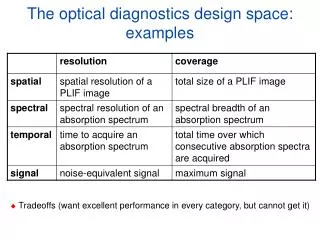
Explore optical diagnostics for tight environments with imaging fibers, components, and innovative illumination methods. Learn about advanced imaging technologies and field of view lenses for enhanced testing.

Comprehensive Optical Diagnostics for Tight Environments: Imaging Fibers & Components Overview
E N D
Presentation Transcript
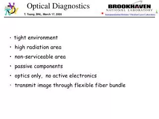
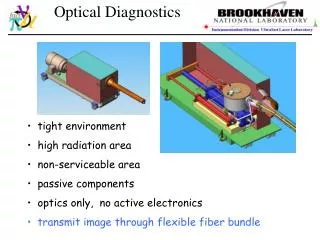
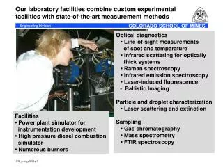
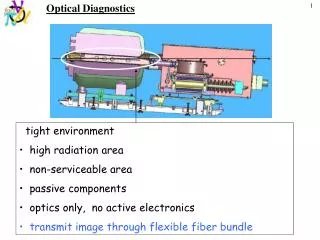
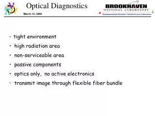
Optical Diagnostics Thomas Tsang • tight environment • high radiation area • non-serviceable area • passive components • optics only, no active electronics • back illuminated with a single fiber laser - pulsed laser X • transmit image through flexible fiber bundle
Optical Diagnostics Nov, 2004 @ Princeton Test target Field of view lens lens fiber bundle
Optical Diagnostics More imaging fibers New imaging fiber bundle Core size: 24 µm, Diameter: 1/4” New imaging fiber bundle Core size: 12 µm, diameter: 1/8” old fiber bundle SMD camera CCD size: 13.4 x 13.4 mm Pixels: 960x960 Single frame: 240x240 pixels Reduced pixel size: 56 x 56 um Total fiber counts ~50,000 in 3.17 mm diameter Imaging ~243 x 243 fibers on 960 x 960 CCD array ~1 imaging fiber on ~4x4 pixels on full frame ~1 imaging fiber on ~1 pixel on a single frame
Optical Diagnostics Simple back illumination ?
Optical Diagnostics Backlight illumination results cm scale test target need >500 pulse/frame ~mJ/pulse in 1-MHz reprate !! fiber backlight laser light input
Optical Diagnostics Conventional shadow illumination approach ? >12-inch away Can NOT be implemented in this tight environment !
Optical Diagnostics retroreflected illumination Spherical mirror laser illumination image collection cm scale Works OK in this tight environment test target
Optical Diagnostics Exp test setup test target • Optical Components • 50/50 beam splitter: Edmund, 0.5 cm cube • spherical mirror: Edmund, f=3-in, D=3in< Au coated • small prism mirror: Edmund, 1x1x1.4 cm, Au coated • large prism mirror: Edmund, 2.5x2.5x3.54 cm. Au coated • imaging fiber Edmund: ⅛-in diameter, 12-µm core, 0.55 NA • illumination fiber: ThorLabs, 0.22 NA, SMA-905 840 -µm core • imaging lens: Sunex, f=0.38-cm, f/# 2.6, diagonal FOV 54°, φ1.4-cm x 2.0 cm
Optical Diagnostics Field of view - imaging
Optical Diagnostics Field of view – NIR laser illumination & imaging
Optical Diagnostics optical design in secondary containment e-Drawing - Van Graves, ORNL e-Drawing - Van Graves, ORNL One set of optics per viewport
Optical Diagnostics An optical chopper in motion @ 4 kHz 100 µs/frame Stationary image 10 µs/frame Velocity @ ~40 meter/sec
Optical Diagnostics Other issues: • Laser power increase to ~40 W/pulse (instead of 10 Watt/pulse) • ~50-m long flexible, square shaped imaging fiber – Schott • Depth of focus → apparent image size variation • 3-in dia. spherical mirror (lens/mirror) with the right focal length • Anti-reflection coated (@ 800 nm) viewports • Number of viewports ? • Location of the viewports ? • How many fast CCD camera ? • Switch from one viewport to the next with one laser/camera system ? • Glass rather than fused silica optics ok ? • …