Download
1 / 46
460 likes | 682 Vues
ECE & TCOM 590 Microwave Transmission for Telecommunications. Microwave Passive Components February 19, 26, 2004. Network Matrices. I 1. I 2. + V 1 -. + V 2 -. Two-Port Device. Low frequency circuits - use Z, Y, H parameters

E N D
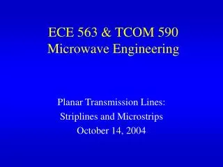
ECE & TCOM 590Microwave Transmission for Telecommunications Microwave Passive Components February 19, 26, 2004
Network Matrices I1 I2 + V1 - + V2 - Two-Port Device Low frequency circuits - use Z, Y, H parameters Z: V1 = z11I1 + z12I2 Y: I1 = y11V1 + y12V2 V2 = z21I1 + z22I2 I2 = y21V1 + y22V2 H: V1 = h11I1 + h12V2 I2 = h21I1 + h22V2
Network Matrices E Y1+ E Y2+ E Y2- E Y1-
Scattering Matrices for a 2 port a1+ a2+ a1- a2-
Physical Interpretation for a 2 port a1+ a2+=0 ZL=ZTE a1- a2- Matched load
Basic Properties of Scattering Matrix Elements (S parameters): Lossless System -
Examples: Tee Junction • Waveguide, coax, stripline, junction with 3 ports and used for power dividers, mixers, sampling junctions • axis of side arm (2) is parallel to E of main guide [(1) to (3)]. Power fed at port 2 appears at (1) & (3) as = magnitude, opposite phase.
Directional Coupler 4 port microwave junction Power in 1 couples to port 2 with a fraction to port 4 and virtually none to 3 Power in 2 couples to port 2 with fraction to 3 and none to 4 All ports well matched so Sii=0
Directional Coupler (D/C) From this S matrix • Power coupled to port 4 is 90o out of phase relative to power at port 2. (Same for power coupled to 3 compared to 1 for power in reverse direction. • Lines 1&2 and 3&4 are identical and any can be used as primary line while others serve as secondary • D/C with c2 small(<<1): widely used for power moni-toring in forward and reverse directions. Reflections from imperfectly matched load or antenna. • D/C with c2 significant fraction of unity used as power dividers
Balanced Amplifier Configuration(ref: Gonzalez, Microwave Transistor Amplifiers)
Branch Line Coupler (ref: Gonzalez, Microwave Transistor Amplifiers)
Lange Directional Coupler • Popular implementation of the quadrature hybrid in microstrip line form. • The interdigital form of the microstrips permits a very compact geometric size and provides for tight coupling. • Typically coupling values range between –5 and – 1 dB. • Octave or more of bandwidth.
TEM Directional Couplers Pair of coupled transmission lines has coupling with wave induced on secondary line is in a direction opposite to that of primary
Coupled Coplanar Striplines Power on a coupled TEM-transmission line propagates as a composite of two possible modes: one even and one odd.