Serial Port / UART of Modern Desktop Board & its Linux programming
480 likes | 808 Vues
Serial Port / UART of Modern Desktop Board & its Linux programming. Dr A Sahu Dept of Comp Sc & Engg . IIT Guwahati. Outline. I/O Port Addressing UART Port Basic 16500 Standardized UART UART Programming in C Loop back program. IO Port Addressing. Standardized Use command

Serial Port / UART of Modern Desktop Board & its Linux programming
E N D
Presentation Transcript
Serial Port / UART of Modern Desktop Board & its Linux programming Dr A Sahu Dept of Comp Sc & Engg. IIT Guwahati
Outline • I/O Port Addressing • UART Port Basic • 16500 Standardized UART • UART Programming in C • Loop back program
IO Port Addressing • Standardized • Use command • $ cat /proc/ioports 0000-001f : dma1 0020-0021 : pic1 0040-0043 : timer0 0050-0053 : timer1 0060-0060 : keyboard 0064-0064 : keyboard 0070-0071 : rtc0 0080-008f : dma page reg 00a0-00a1 : pic2 00c0-00df : dma2 00f0-00ff : fpu 0170-0177 : 0000:00:14.1 0170-0177 : pata_atiixp 01f0-01f7 : 0000:00:14.1 01f0-01f7 : pata_atiixp 0200-020f : pnp 00:09 0220-0233 : pnp 00:09 0240-0253 : pnp 00:09 0260-0273 : pnp 00:09 0280-0293 : pnp 00:09 02f8-02ff : serial 0376-0376 : 0000:00:14.1 0376-0376 : pata_atiixp 0378-037a : parport0 0388-0389 : pnp 00:09 03c0-03df : vga+ 03f6-03f6 : 0000:00:14.1 03f6-03f6 : pata_atiixp 03f8-03ff : serial 040b-040b : pnp 00:09 04d0-04d1 : pnp 00:09
IOPL • IO Privilege level • Can be set by root • If set user can RW to Ios • Loopback user C/C++ program can access Modem/UART at address 03F8
Type of Serial Communication • Synchronous • Sender and receiver must synchronize • Done in hardware using phase locked loops (PLLs) • Block of data can be sent • More efficient : Less overhead than asynchronous transmission • Expensive • Asynchronous • Each byte is encoded for transmission • Start and stop bits • No need for sender and receiver synchronization
Type of Serial Communication Transmission Gaps Sender Receiver a Data Data Data Asynchronous transmission CLK Sender Receiver Data Data Data Data Data Synchronous transmission
Framing in Asynchronous • Character oriented • Each character carried start bit and stop bits • When No data are being transmitted • Receiver stay at logic 1 called mark, logic 0 is Space • Framing: • Transmission begins with one start bit (low/0) • Followed by DATA (8bit) and • Stop bits (1 or 2 bits of logic high)
Type of Serial Communication Asynchronous transmission 1 start bit 1 or 2 Stop bit Source data 1 0 0 0 1 1 1 0 LSB MSB Time Start Bit Start Bits 8 bit Data
Using ‘echo’ and ‘cat’ • Your device-driver module (named ‘uart.c’) is intended to allow unprivileged programs that are running on a pair of adjacent PCs to communicate via a “null-modem” cable Transmitting… Receiving… $ echo Hello > /dev/uart $ _ $ cat /dev/uart Hello _
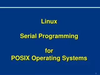
Tx and Rx • The UART has a transmission-engine, and also a reception-engine, which are able to operate simultaneously (i.e., “full-duplex”) • Software controls the UART’s operations by accessing several registers, using the x86 processor’s ‘in’ and ‘out’ instructions • Linux provides some convenient ‘macros’ that ‘hide’ the x86 machine-code details
Linux char-driver components Device-driver LKM layout module’s ‘payload’ is a collection of callback-functions having prescribed prototypes function function function AND a ‘package’ of function-pointers fops . . . the usual pair of module-administration functions init registers the ‘fops’ exit unregisters the ‘fops’
Requires a device-file node • Our System Administrator has created the device-file needed for your driver-module: root# mknod /dev/uart c 84 0 root# chmod a+w /dev/uart • Your driver-module needs to ‘register’ your package of driver-methods (i.e., functions) in its initialization routine (and ‘unregister’ them later in its cleanup routine)
Serial data-transmission The Transmitter Holding Register (8-bits) Software outputs a byte of data to the THR The bits are immediately copied into an internal ‘shift’-register The bits are shifted out, one-at-a-time, in sync with a clock-pulse 0 1 1 0 0 0 0 1 0 1 1 0 0 0 0 1 1-0-1-1-0-0-0-0-1-0 data-bits The transmitter’s internal ‘shift’ register clock stop bit start bit clock-pulses trigger bit-shifts
‘write()’ and ‘read()’ • Obviously your driver-module’s ‘payload’ will have to include ‘methods’ (functions) which perform the ‘write()’ and ‘read()’ operations that applications will invoke • You may decide your driver needs also to implement certain additional ‘methods’ • A little history is helpful for understanding some of the UART device’s terminology
Serial data reception input voltage clock clock-pulses trigger voltage-sampling and bit-shifts at regular intervals The receiver’s internal ‘shift’ register 0 1 1 0 0 0 0 1 1-0-1-1-0-0-0-0-1-0 data-bits stop bit start bit Software can input the received byte from the RBR 0 1 1 0 0 0 0 1 The Receiver Buffer Register (8-bits)
8251 Block Diagram Internal Line Data Bus Buffer Transmit Buffer D7-D0 TXD RESET CLK C/Db RDb WRb CSb R/W Control Logic TXRDY TXE TXC Transmit Control DSRb DTRb CTSb RTSb Modem Control Receive Buffer RXD Receive Control RXRDY RXC SYBDET/BD
Transmitter and Receiver Internal Data Bus Out put Register TxD TxCb TxRDY TxE Transmitter Buffer Register Data Buffer Register D0 D7 Transmitter Control Logic Input Register RxD RxCb RxRDY Receiver Buffer Register Receiver Control Logic
Command Register (Command Word Format) EH IR RTS ER SBRK RxE DTR TxE TxE: transmit enable (0/1 Enable Disable) DTR: data terminal ready (1=ENABLE DTR) RxE: receiver enable (1/0=EN/DISABLE) SBPRK: send break character 1= force TxD low ER: error reset (Reset Flags: Parity ,Over run, Framing Error of Status Word) RTS: request to send (1= Enable Request to send) IR: internal reset (Reset 8251 to mode) EH: enter hunt mode (1=search for Sync Character)
DSR SYN DET FE OE PE Tx EMPTY RxRDY TxRDY 8251: Status Regsiter TxRDY transmit ready (DB Buffer is empty) RxRDY receiver ready TxEMPTY transmitter empty PE parity error (1=when PE detected) OE overrun error FE framing error (Aynsc only, Valid stop bit not detected) SYNDET sync. character detected DSR data set ready (DSR set at 0 level)
PC Standard UART (16550) Registers Base+0 Divisor Latch Register 16-bits (R/W) Base+0 Transmit Data Register 8-bits (Write-only) Base+0 Received Data Register 8-bits (Read-only) Base+1 Interrupt Enable Register 8-bits (Read/Write) Base+2 Interrupt Identification Register 8-bits (Read-only) Base+2 FIFO Control Register 8-bits (Write-only) Base+3 Line Control Register 8-bits (Read/Write) Base+4 Modem Control Register 8-bits (Read/Write) Base+5 Line Status Register 8-bits (Read-only) Base+6 Modem Status Register 8-bits (Read-only) Base+7 Scratch Pad Register 8-bits (Read/Write)
Rate of data-transfer • The standard UART clock-frequency for PCs equals 1,843,200 cycles-per-second • Each data-bit consumes 16 clock-cycles • So the fastest serial bit-rate in PCs would be 1843200/16 = 115200 bits-per-second • With one ‘start’ bit and one ‘stop’ bit, ten bits are required for each ‘byte’ of data • Rate is too fast for ‘teletype’ terminals
Divisor Latch • The ‘Divisor Latch’ may be used to slow down the UART’s rate of data-transfer • Clock-frequency gets divided by the value programmed in the ‘Divisor Latch’ register • Older terminals often were operated at a ‘baud rate’ of 300 bits-per-second (which translates into 30 characters-per-second) • So Divisor-Latch set to 0x0180
How timing works Transmitter clock (bit-rate times 16) DATA OUT start-bit data-bit 0 data-bit 1 … 24 clock-cycles 16 clock-cycles 16 clock-cycles sample sample Receiver clock (bit-rate times 16) receiver detects this high-to-low transition, so it waits 24 clock-cycles, then samples the data-line’s voltage every 16 clock-cycles afterward
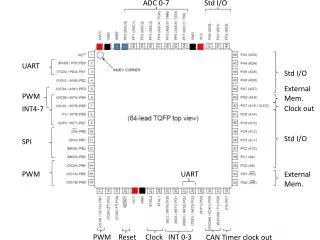
Programming interface The PC uses eight consecutive I/O-ports to access the UART’s registers 0x03F8 0x03F9 0x03FA 0x03FB 0x03FC 0s03FD 0x03FE 0x03FF RxD/TxD IER IIR/FCR LCR MCR LSR MSR SCR interrupt enable register line status register modem status register receive buffer register and transmitter holding register (also Divisor Latch register) line control register modem control register scratchpad register interrupt identification register and FIFO control register
Modem Control Register 7 6 5 4 3 2 1 0 0 0 0 LOOP BACK OUT2 OUT1 RTS DTR Legend: DTR = Data Terminal Ready (1=yes, 0=no) RTS = Request To Send (1=yes, 0=no) OUT1 = not used (except in loopback mode) OUT2 = enables the UART to issue interrupts LOOPBACK-mode (1=enabled, 0=disabled)
Modem Status Register 7 6 5 4 3 2 1 0 DCD RI DSR CTS delta DCD delta RI delta DSR delta CTS set if the corresponding bit has changed since the last time this register was read Legend: [---- loopback-mode ----] CTS = Clear To Send (1=yes, 0=no) [bit 0 in Modem Control] DSR = Data Set Ready (1=yes, 0=no) [bit 1 in Modem Control] RI = Ring Indicator (1=yes,0=no) [bit 2 in Modem Control] DCD = Data Carrier Detected (1=yes,0=no) [bit 3 in Modem Control]
Line Status Register 7 6 5 4 3 2 1 0 Error in Rx FIFO TXmitter idle THR empty Break interrupt Framing error Parity error Overrun error Received Data Ready These status-bits indicate errors in the received data This status-bit indicates that the data-transmission has been completed This status-bit indicates that the Transmitter Holding Register is ready to accept a new data byte This status-bit indicates that a new byte of data has arrived (or, in FIFO-mode, that the receiver-FIFO has reached its threshold)
Line Control Register 7 6 5 4 3 2 1 0 Divisor Latch access set break stick parity even parity select parity enable number of stop bits word length selection 00 = 5 bits 01 = 6 bits 10 = 7 bits 11 = 8 bits 0 = 1 stop bit 1 = 2 stop bits 0 = normal 1 = ‘break’ 0 = no parity bits 1 = one parity bit 0 = not accessible 1 = assessible 1 = even parity 0 = ‘odd’ parity
Interrupt Enable Register 7 6 5 4 3 2 1 0 0 0 0 0 Modem Status change Rx Line Status change THR is empty Received data is available If enabled (by setting the bit to 1), the UART will generate an interrupt: (bit 3) whenever modem status changes (bit 2) whenever a receive-error is detected (bit 1) whenever the transmit-buffer is empty (bit 0) whenever the receive-buffer is nonempty Also, in FIFO mode, a ‘timeout’ interrupt will be generated if neither FIFO has been ‘serviced’ for at least four character-clock times
FIFO Control Register 7 6 5 4 3 2 1 0 RCVR FIFO trigger-level reserved reserved DMA Mode select XMIT FIFO reset RCVR FIFO reset FIFO enable 00 = 1 byte 01 = 4 bytes 10 = 8 bytes 11 = 14 bytes Mode: If supported DMA Writing 1 empties the FIFO, writing 0 has no effect Writing 0 will disable the UART’s FIFO-mode, writing 1 will enable FIFO-mode
Interrupt Identification Register 7 6 5 4 3 2 1 0 0 0 ‘highest priority’ UART Interrupt still pending 00 = FIFO-mode has not been enabled 11 = FIFO-mode is currently enabled highest 011 = receiver line-status 010 = received data ready 100 = character timeout 001 = Tx Holding Reg empty 000 = modem-status change lowest 1 = No UART interrupts are pending 0 = At least one UART interrupt is pending
Responding to interrupts • You need to ‘clear’ a reported interrupt by taking some action -- depending on which condition was the cause of the interrupt: • Line-Status: read the Line Status Register • Rx Data Ready: read Receiver Data Register • Timeout: read from Receiver Data Register • THRE: read Interrupt Identification Register or write to Transmitter Data Register (or both) • Modem-Status: read Modem Status Register
Usage flexibility • A UART can be programmed to operate in “polled” mode or in “interrupt-driven” mode • While “Polled Mode” is simple to program • It does not make efficient use of the CPU in situations that require ‘multitasking’ (as the CPU is kept busy doing “polling” of the UART’s status instead of useful work
How to transmit a byte Read the Line Status Register Transmit Holding Register is Empty? NO YES Write byte to the Transmitter Data Register DONE
How to receive a byte Read the Line Status Register Received Data is Ready? NO YES Read byte from the Receiver Data Register DONE
How to implement in C/C++ // declare the program’s variables and constants char inch, outch = ‘A’; // --------------------- Transmitting a byte ------------------- // wait until the Transmitter Holding Register is empty, // then output the byte to the Transmit Data Register do { } while ( (inb( LINE_STATUS) & 0x20) == 0 ); outb( outch, TRANSMIT_DATA_REGISTER ); // ---------------------- Receiving a byte ------------------------ // wait until the Received Data Ready bit becomes true, // then input a byte from the Received Data Register do { } while ( (inb( LINE_STATUS ) & 0x01 ) == 0 ); inch = inb( RECEIVED_DATA_REGISTER );
How to initialize ‘loopback’ mode Set the Divisor Latch Access Bit in the Line Control Register Write a nonzero value to the Divisor Latch Register Clear the Divisor Latch Access Bit and specify the desired data-format in the Line Control Register Set the Loopback bit in the Modem Control Register DONE
How to adjust the cpu’s IOPL • IO Privilege Level • Linux provides a system-call to privileged programs which need to access I/O ports • The <sys/io.h> header-file prototypes it, and the ‘iopl()’ library-function invokes it • The kernel will modify the CPU’s current I/O Permission Level in cpu’s EFLAGS (if the program’s owner has ‘root’ privileges) • First execute our ‘iopl3’ command • Use Root mode to do this
Loop-Back Experiment • Download and run our ‘testuart.cpp’ demo • It uses the UART’s ‘loopback’ test mode to ‘receive’ each character that it ‘transmits’ UART ‘loopback’ mode TxShiftReg TxData RxShiftReg RxData Output loops back to become input The external signal-lines are bypased
Loop Back Program: uarttest.cpp #define UART_PORT 0x03F8 // base port-address for the UART #define DIVISOR_LATCH (UART_PORT + 0) #define TX_DATA_REG (UART_PORT + 0) #define RX_DATA_REG (UART_PORT + 0) #define LINE_CONTROL (UART_PORT + 3) #define MODEM_CONTROL (UART_PORT + 4) #define LINE_STATUS (UART_PORT + 5) char msg[] = "\n\tThis is a test of the UART's loopback mode\n"; int main( intargc, char **argv ) { // set the CPU's I/O Permission-Level to allow port-access if ( iopl( 3 ) ) { perror( "iopl" ); exit(1); }
Loop Back Program // establish the UART's operational parameters outb( 0x80, LINE_CONTROL ); // set DLAB=1 outw( 0x0001, DIVISOR_LATCH ); // set 11520 baud outb( 0x03, LINE_CONTROL ); // set data-format: 8-N-1 outb( 0x10, MODEM_CONTROL ); // turn on 'loopback' mode // write each message-character, read it back, and display it for (inti = 0; i < sizeof( msg ); i++) { do { } while ( (inb( LINE_STATUS )&0x20) == 0x00 ); outb( msg[i], TX_DATA_REG ); do { } while ( (inb( LINE_STATUS )&0x01) == 0x00 ); int data = inb( RX_DATA_REG ); printf( "%c", data ); } outb( 0x00, MODEM_CONTROL );// turn off 'loopback' mode printf( "\n" ); }