Download
1 / 26
260 likes | 279 Vues
This overview provides information on monitoring methods for transformers, including dissolved gas analysis (DGA), acoustic detection, torque monitoring, and cooling system efficiency. It also explains the significance of different gases in DGA and the use of DGA for condition-based monitoring.

E N D
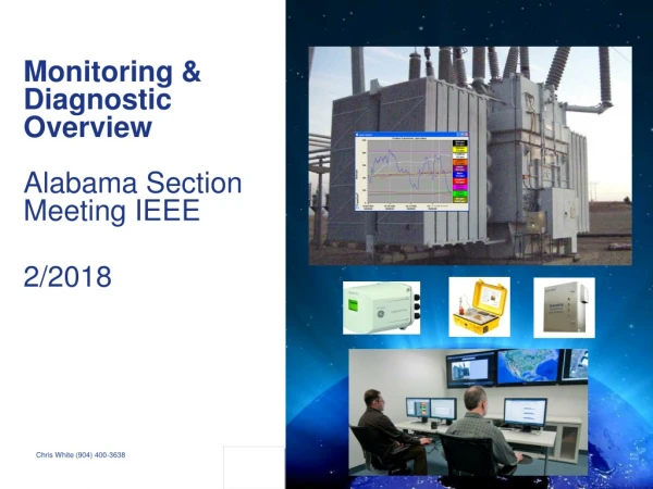
Monitoring & • Diagnostic Overview • Alabama Section Meeting IEEE • 2/2018 • Chris White (904) 400-3638
The Transformer … A Complex System Bushings Cooling System • Main tank • Core • Coils • Oil Control Cabinet Tap changer P&C Education Seminar
Bushings Tap changer Cooling System Tank Oil Coils Control Cabinet Core Transformer Construction
Transformer Failure Modes • Component Failure rates • Monitoring method(Not cost of failure) • Main Tank 30% DGA monitoring of main tank Winding & oil temperature Acoustic PD PD recognition algo from BMT300 (next Gen) SFRA • Tap changer 35% DGA of diverter and tap changer tanks Tap Changer models Motor torque monitoring Acoustic signature analysis Tap changer control • Bushing 15% Tan delta Partial discharge PD recognition algo from BMT300 (next Gen) • Cooling System5% Cooling efficiency models Cooling control Oil flow Source of data: The Hartford Steam Boiler Inspection and Insurance Co. 4
First, What Is Transformer Dissolved Gas Analysis? SampleTestDocDiagnosis Doctors extract information about our health from our blood. Technicians extract information about the health of our transformers from the oil via DGA. Substations are more challenging for this sampling process than a doctor’s office .
Transformer Dissolved Gas Analysis, The Process & Logic Duvall’s Triangle SampleTestTechDiagnosis We prefer a clean sample with no issues detected, just as a blood test in a doctor’s office.
Transformer Operating Temperatures • 20 – 80 C? First signs of gassing begins around 100 C with CO2 & CO. First signs of hot metal gases begins around 150 C.
What Are The Relevant Gases? “Paper & Oil Gases” “Hot Metal Gases”
H C C C C C H H H H H H H H H H H H H H H H H H H H H H H H H H H H H H H H H C C C C C C H H H C C C C C C H H H H H H H H H Oil degradation – Typical oil Molecule P&C Education Seminar
CH2OH O CHO H CARBONMONOXIDE WATER O H H O H H C OH H O H H OH FURAN WATER WATER Paper degradation – gases developed CO HOH HOH Paper Molecule HOH P&C Education Seminar
Key DGA gasses, and what they indicate P&C Education Seminar
Why Dissolved Gas Analysis? • By identifying which gas is increasing it is possible to determine the likely nature of the anomaly without having to shut down the transformer. • Enables operational decisions based on this information. • On-line DGA monitors with remote communications enable true Condition Based Monitoring (CBM) and decision making without going to site. P&C Education Seminar
Where’s The Problem? • Nitrogen Sealed #2 – 30 MVA • Nitrogen Sealed #1 – 36 MVA
Where’s The Problem? Continued • Ratio of CO2/CO gases decreased from 7:1 to 5:1 after the event • Ratio of CO2/CO gases decreased from 117:1 to 2:1 after the event aaajjjjjjjjjjjjjjjjjaaaaaa aaaaaaaaaaaaaaaaa
Where’s The Problem? Continued • Winding Failure #1 • Primary Lead – Repairable #2 Transformer Replaced Transformer Repaired
Where’s The Problem? 2% Decline Overall 38% Increase Overall DETC Coked
15 MVA, 100 kV – Manufactured 1999 - Post-Fault 77% Drop in 1 Year
1999, 15 MVA, 100 kV, Complete Picture 96% Drop 2011 - 2016
Acetylene Is Problematic, But Is It Fatal? • Not always: • Is it present due to activity in the winding insulation, or is it bare metal? • The problem could be easy to get to and simple to repair. • Transformers have been discarded when the problem was a simple fix, but that was unknown at the time. • It can mean the difference between a few thousand dollar$ in repairs, versus a few million dollar$ in potential replacement costs.
Summary/Conclusion • All internal faults are not fatal. • Know your fleet. It will only be beneficial in solving the diagnostic puzzles as they present themselves. • All faults are not as easily identified. Don’t give up, as there is an answer. Allow software help with the data analysis and direct you to the critical assets and information, which are now available. • Trending the fluctuations of gas concentration, rate of change and ratios is very important for understanding your transformers’ vital signs. • Know when to reach out for additional support, if needed. • We are all in this together.


