Detention Basics
Detention Basics. www.b-e-c.com/PromoPages/GatewayBrownfields4.jpg. http://emengineers.com/images/Wh2o1lo.jpg. Objectives. Know what a detention basin is Know how to develop an inflow hydrograph Know how to determine a stage-storage curve Know how to determine an outflow curve.


Detention Basics
E N D
Presentation Transcript
Detention Basics www.b-e-c.com/PromoPages/GatewayBrownfields4.jpg http://emengineers.com/images/Wh2o1lo.jpg
Objectives • Know what a detention basin is • Know how to develop an inflow hydrograph • Know how to determine a stage-storage curve • Know how to determine an outflow curve
/www.dfo-mpo.gc.ca/canwaters-eauxcan/infocentre/guidelines-conseils/factsheets-feuillets/nfld/images/fact17_e/4-7.jpg/www.dfo-mpo.gc.ca/canwaters-eauxcan/infocentre/guidelines-conseils/factsheets-feuillets/nfld/images/fact17_e/4-7.jpg
Detention Basin-Purposes • Store water temporarily during a storm and release the stored water slowly • Attenuate the flow • Store first-flush • Design for infiltration • If all water is infiltrated then (retention basin)
Detention Basins • On-Site • Regional
Detention Basins • Inflow (ditch or pipe) • Storage • Outflow (single/multiple stage • Orifice • Weir • Emergency spillway
Routing • Method used to model the outflow hydrograph • Based on continuity equation • Water in varies • Water out varies
Information Needed to Route • Inflow hydrograph • Relation of storage volume to elevation in the proposed detention basin • Relation of outflow to water level elevation (discharge rating)
Inflow hydrograph • Ch 5 of TR-55 (NRCS method) • Modified rational method (see book 11.2) • Simple symmetrical triangle (2*tc) • Asymmetrical triangle (total base = 2.67 tc)
TR-55 Hydrograph(NRCS Method) Peak flow is higher after development Peak flow occurs earlier after development
Rational Method:Time base of 2.67 tc Area under hydrograph?
Computing Storage Volumes • Two Methods • Elevation-Area (detention basins) • Average End-Area (pipes)
Computing Storage Volumes Elevation-Area (detention basins) Contour lines are determined around basin Determine area of each contour Volume between 2 contours = average area*depth between the contours Prepare a table showing elevation, area, incremental volume and cumulative volume See example 14-1 (page 341) 14
Computing Storage Volumes • Average end-area (pipes) • Find u/s area at elevation increments • Find d/s area at elevation increments • Average the areas & multiply by length • This gives you total volumes (not incremental volumes) • See Example 14-2 (page 343)
Discharge Rating • Calculate outflows based on water elevation in the detention pond • Orifice and weir equations are used • Single stage (see pg 345) • Two stage (see page 348) • If more than one stage, calculate each outlet separately and add to get stage-discharge curves
Orifices Hole in a wall through which water flows Square edge Beveled edge 21
Orifice When water flows through an orifice the water contracts with a smaller area than the original orifice opening (vena contracta) www.spiraxsarco.com www.diracdelta.co.uk 22
General Orifice Equation Q=ca(2gh).5 Where: Q=discharge (cfs or cms) c=discharge coefficient (0.62 often used) a=cross-sectional orifice area (sq ft or sq meters) h=total head (ft or m) g=gravitational constant (32.2 or 9.81) 23
Orifice Discharge Free Discharge Submerged Discharge Equation is the same. Head for the submerged discharge is the difference between upper and lower water surfaces 24
Orifice-Free Discharge Given: Dia=6”, WSE=220.0 ft; Elev of orifice centerline=200.0 ft Q=ca(2gh).5 Q=0.62*0.196*(2*32.2*20).5 Q=4.4 cfs 25
Weir Horizontal surface over which water is allowed to flow Used to regulate and measure flows http://www.flow3d.com/appl/weir.htm 26
Rectangular, Sharp-Crested Weir Q=cLH3/2 Q-flow (cfs) c-adjusted discharge coefficient (careful) c=3.27+0.4(H/P) where P is ht of weir above channel bottom L-effective crest length, ft L=L’-0.1nH L’=actual measured crest length and n=# of contractions H-head above crest, ft 27
Rectangular, Broad-Crested Weir Q=cLH3/2 Q-flow (cfs) c-discharge coefficient (App A-5 English units) L-crest length, ft H-head above crest, ft 28
V-Notch or Triangular Weir Q=c*tan(angle/2)*H5/2 c = 2.5 (but should calibrate) 29
Other Weir Types Cipoletti (trapezoidal) Ogee (dam spillway) youngiil.co.kr www.lmnoeng.com 30
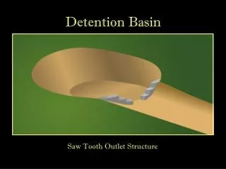
Detention Outlet Structures Single Stage (culvert or orifice) Multi-Staged to handle different flows Combination of orifices &/or weirs 31
Single Stage Outlet Example (Ex14-3) An outlet consisting of a 12” pipe is proposed for a detention basin. The invert of the pipe is 320.0 feet and the top of berm is 325.0 ft. Compute the discharge rating for the outlet. Area=0.785 sq ft Assume c=0.62 Use orifice equation: Q=ca(2gh).5 32
Multi-Stage Outlet Example 14-4 (pg 349) 4” Orifice and 2 weirs L=1.5’ and L=12.5’ 35
Emergency Spillway • Emergency Outlet • Rainfall exceeds design storm • Outlet becomes blocked • Purpose • Prevent overtopping of berm • Control direction of overflow
Emergency Spillway Typical Design Criteria Spillway crest set at or above the maximum impoundment elev Designed for emergency spillway design storm (minus what can be handled by outflow structure) or designed to convey peak discharge of design storm (assuming outflow structure plugged) Top of berm = WSE through the spillway + freeboard (1-2’ typical)