Download
1 / 66
710 likes | 1.11k Vues
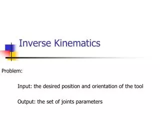
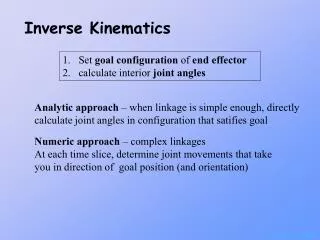
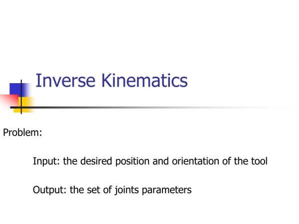
Inverse Kinematics. Set goal configuration of end effector calculate interior joint angles. Analytic approach – when linkage is simple enough, directly calculate joint angles in configuration that satisfies goal. Numeric approach – complex linkages

E N D
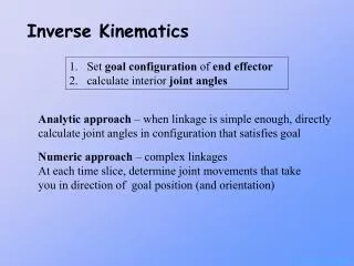
Inverse Kinematics Set goal configuration of end effector calculate interior joint angles Analytic approach – when linkage is simple enough, directly calculate joint angles in configuration that satisfies goal Numeric approach – complex linkages At each time slice, determine joint movements that take you in direction of goal position (and orientation)
Forward Kinematics - review Articulated linkage – hierarchy of joint-link pairs Pose – linkage is a specific configuration Pose Vector – vector of joint angles for linkage Degrees of Freedom (DoF) – of joint or of whole figure Types of joints: revolute, prismatic • Tree structure – arcs & nodes • Recursive traversal – concatenate arc matrices • Push current matrix leaving node downward • Pop current matrix traversing back up to node
Inverse Kinematics End Effector L1 q3 q2 L3 L2 q1 Goal
Inverse Kinematics Underconstrained – if fewer constraints than DoFs Many solutions Overconstrained – too many constraints No solution Reachable workspace – volume the end effector can reach Dextrous workspace – volume end effector can reach in any orientation
Inverse Kinematics - Analytic Given arm configuration (L1, L2, …) Given desired goal position (and orientation) of end effector: [x,y] or [x,y,z, y1,y2, y3] Analytically compute goal configuration (q1,q2) Interpolate pose vector from initial to goal
Analytic Inverse Kinematics q2 L2 Goal L1 (X,Y) q1
Analytic Inverse Kinematics Multiple solutions Goal (X,Y)
Analytic Inverse Kinematics L2 180- q2 L1 (X,Y) q1 qT
Analytic Inverse Kinematics L2 180- q2 L1 (X,Y) q1 Y qT X
Law of Cosines C A a B
Analytic Inverse Kinematics L2 (X,Y) L1 180- q2 q1 qT Y X
Iterative Inverse Kinematics When linkage is too complex for analytic methods At each time step, determine changes to joint angles that take the end effector toward goal position and orientation Need to recompute at each time step
Inverse Jacobian Method a2 d2=EF-J2 End Effector a2 x d2 q2 - Compute instantaneous effect of each joint - Linear approximation to curvilinear motion - Find linear combination to take end effector towards goal position
Inverse Jacobian Method Instantaneous linear change in end effector for ith joint = (EF - Ji) x ai
Inverse Jacobian Method What is the change in orientation of end effector induced by joint i that has axis of rotation ai and position Ji? Angular velocity
Inverse Jacobian Method Solution only valid for an instantaneous step Angular affect is really curved, not straight line Once a step is taken, need to recompute solution
Set up equations yi: state variable xi : system parameter fi : relate system parameters to state variable Inverse Jacobian Method - Mathematics
Matrix Form Inverse Jacobian Method - Mathematics
Inverse Jacobian Method - Mathematics Use chain rule to differentiate equations to relate changes in system parameters to changes in state variables
Inverse Jacobian Method - Mathematics Matrix Form
Change in position (and orientation) of end effector Change in joint angles Linear approximation that relates change in joint angle to change in end effector position (and orientation) Inverse Jacobian Method
= (S - J1) x a1 = w1 Inverse Jacobian Method
The Matrices N DoFs V – desired linear and angular velocities 3x1, 6x1 J – Jacobian Matrix of partials 3xN, 6xN N x 1 q – change to joint angles (unknowns)
LU decomposition Solving using the Pseudo Inverse
A solution of this form When put into this formula Like this After some manipulation, you can show that it… …doesn’t affect the desired configuration Adding a Control Term But it can be used to bias The solution vector
Desired angles and corresponding gains are input ‘z’ is H differentiated Form of the Control Term Bias to desired angles (not the same as hard joint limits) Where the deviation is large, you bump up the solution vector in such a way that you don’t disturb the desired effect
Include this in equation Isolate vector of unknown Rearrange to isolate the inverse Some Algebraic Manipulation
LU decomp. Solving the Equations
Control Term Use to bias to desired mid-angle Does not enforce joint angles Does not address “human-like” or “natural” motion Only kinematic control – no forces involved
Jacobian Transpose Use projection of effect vector onto desired movement
Alternate Jacobian G Use the goal postion instead of the end-effector!!?? !? …
substitution Solve Damped Least Squares G
Hueristic Human-Like Linkage (HAL) 7 DoF linkage RA (q1,q2 ,q3) , RB ( q4), RC(q5,q6 ,q7) 3 DoF G Decompose into simpler subproblems 1 DoF Set hand position and rotation based on relative position of Goal to shoulder 3 DoF Fix wrist position – use as Goal
L L1 L2 Hueristic Human-Like Linkage (HAL) s Set q4 based on distance between shoulder and wrist w e Assume axis of elbow is perpendicular to plane defined by s, e, w use law of cosines
Hueristic Human-Like Linkage (HAL) s q4 w e Elbow lies on circle defined by w, s & q4 Determine elbow position based on heuristics For example: project forearm straight from hand orientation if arm intersects torso or a shoulder angle exceeds joint limit (or exceeds comfort zone) – Clamp to inside of limits
Hueristic Human-Like Linkage (HAL) s q4 w e From e and s, determine RA From e and w and hand orientation, determine RB
Cyclic-Coordinate Descent Rotational joint: .
Cyclic-Coordinate Descent Rotational joint: .
Cyclic-Coordinate Descent Rotational joint: .
Cyclic-Coordinate Descent Rotational joint: .