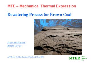
Mechanical and Thermal issues
Mechanical and Thermal issues. Paolo Pierini INFN Sezione di Milano LASA. Mechanical & Thermal Issues.

Mechanical and Thermal issues
E N D
Presentation Transcript
Mechanical and Thermal issues Paolo Pierini INFN Sezione di Milano LASA
Mechanical & Thermal Issues • “Mandate” for the talk:General mechanical and thermal considerations for SRF cryomodules, modeling tools, stress analysis, tuning, alignment, impact of the accelerator environment, issues and input for LHC crab cavity designs • Lot of issues • Concentrate on some issues for Phase I • “Disclaimer”All this is from the point of view of a person not currently involved in the LHC-CC work & collaboration • Participated to design, and engineering of cavities & cryomodules • e-: TTF/FLASH/ILC/XFEL • High power proton linacs (SNS, ADS, SPL, ...) PP
Main constraints • No deep assessment of these technical issues is possible before at least a conceptual design of the whole system is available • The conceptual design cannot be performed without precise boundary conditions • Geometrical, mechanical • Beam dynamic considerations • Alignment requirements • Beam separation • Longitudinal available space • Functional, cryogenics • Limits on additional heat loads from crab-module • Requires heat load budget at various temperature levels • Evaluation of the subsystems needed to provide the desired cryogens, which will in turn need space & design & integration with existing hardware PP
Heat load budget • Cryomodule design is a practice at the boundary between beam dynamics and RF, mechanical, cryogenic engineering considerations • Currently the complete picture is missing, I have seen only estimations of dynamic RF loads due to main crabbing mode • need estimate on static load of module • heat load due to LOM, SOM, HOM couplers, both for static and dynamic conditions • The proposed LOM, SOM, HOM couplers will give unprecedented complications for the design of a He Vessel, alignment scheme, tuning action and thermal design • discussion on constraints of the mass flow that can be taken from QRL cryo lines, and the compatibility of the various operation modes (cooldown/warmup, crab cavity standby and crab cavity operation) PP
2 K vs 4.5 K • There is more than RF losses on the operating mode... • 2 K operation requires more attention to all conduction paths to the bath • Crab Cavities are more complex than usual (LOM, SOM and HOM couplers lead to heat inleak to cavity) • Thermalization at 4.5 K level close to vessel is mandatory • The use of the evaporated gas from the bath for the thermalization, possible in 4.5 K operation (e.g. KEKB), seems difficult for 2 K (Pressure drop, cooling with low pressure vapor at low flows) • Vessel Jacketing • Magnetic shield • Fixed point for alignment • Static/Dynamic load estimations of all couplers PP
Main RF losses: Q0=G/Rs • Using Hasan fit for the BCS surface resistance • we have approx 4 nOhm @ 2 K and 249 nOhm @ 4.5 K, i.e. a factor of over 60 in nominal deposited power at cold • We then have to take into account the residual resistance term (quality of the surface preparation) which contributes to Rs • and any trapped flux • Complex geometry surfaces usually lead to higher residual resistance contribution (chemistry, HPR, ...) PP
Cryo efficiency • Roughly speaking, considering efficiency of cycle • 800 W/W at 2 K (20% Carnot) • 220 W/W at 4.5 K (30% Carnot) • From an efficiency point of view at 800 MHz a bad surface can rapidly spoil any advantage of 2 K • Unshielded earth field Rmag~80nOhm • seems substantial even at 4.5 K, need shield? • This only for main RF load, balance need to take into account full heat load budget PP
More on residual resistance • Accounting only BCS Contribution, for G=260 Ohm (pillbox value), for the main RF load • At 2 K QBCS=6.28 E10 (i.e. < 1 W @ 2 K) • At 4.5 K QBCS=1.04 E9 (i.e. 50 W @ 4.5 K) • Considering a contribution of the residual resistance at the cavity surface of 50 nOhm (complex geometry) • At 2 K Q=4.8 E9 (i.e. 11 W @ 2 K) • At 4.5 K Q=8.7 E8 (i.e. 60 W @ 4.5 K) • hardly a factor 2 difference when accounting cryo efficiency • Typical TESLA-like experience (where it is really needed): Rres from a few nOhm to 10-20 • “...a well prepared Nb surface can reach 10 to 20 nOhm. The record values are near to 1 nOhm”. From HP book. PP
Cooling strategy: 2K ~30 mbar PP
2 K: Needed circuits • 2 K operation via QRL Line C, through J-T valve + counterflow heat exchanger • return gas to low pressure line B • relief for overpressure condition? Possibly not to 20 K return line, to avoid risk of pressurizing He Vessels (cavity plastic detuning) • Thermal sinking at 5 K for all couplers • additional cooling circuit from Line C: 5 K, 3 bar line B, returning to the Line-D (20 K, 1.3 bar), as suggested by TP? • “one could take a very low flow rate for a thermal intercept and allow warming up to 20 K” • Thermal shield using the 50-75 K circuit of line E-F • possibly providing a second sinking for couplers • Need to provide a cooldown-warmup line with controlled temperature decrease to limit thermal gradients in structure (keep aligned and safe...) PP
4.5 K: Needed circuits • 4.5 K operation via QRL Line C • return gas to line D: 20 K return line, but with back pressure control valve to avoid risk of pressurizing He Vessels (permanent cavity detuning) • relief line, needed as for 2 K • Thermal sinking for couplers • additional cooling circuit from Line C: 5 K, 3 bar line B, returning to the Line-D (20 K, 1.3 bar)? • Thermal shield using the 50-75 K circuit of line E-F • possibly providing a second sinking for couplers • But also in this case, need to provide a cooldown-warmup line with controlled temperature decrease to limit thermal gradients in structure PP
mass flow calculations Cryogenic table “à la TP” Comment: SRF cryomodules have large dynamic (RF on/off) loads also on the higher temperature circuits. PP
Need to provide estimations for heat inleak • Static loads • by convection, conduction and radiation • Provide insulating vacuum • Provide thermal intercept to limit conduction paths to 2K He • Provide thermal shield and MLI • Dynamic loads • in the case of a SRF cavity, these are related to RF losses on cavity surface and contributed by coupler(s) • e.g. from ILC TP spreadsheet (Jan 2009) couplers/HOM induced loads are • 20% of the 2 K total dynamic load • 80% of the 5-8 K and 40-80 K total dynamic load • e.g. SNS heat load budget main coupler/HOM is approx 20% of total dynamic load PP
operation modes • Module cooldown/warmup • when the rest of LHC is cold • typically more critical situation for design assessment, concerning stresses under pressure conditions (pressurized flow, warm material properties, possibility of large thermal gradients, ...) • LHC normal operation with crab cavity cold and “off” • detuned • static losses plus any beam induced cavity excitation • LHC crabbing operation • RF on, full static/dynamic losses • Evaluate all these with respect to cryo system and lines PP
Conduction paths • KEKB cavity does not require additional conduction paths to the He vessel for HOM/LOM/SOM, and all power is carried out to the mode dampers out of the cryostat space through the beam line • Also, tuner is integrated into coaxial coupler at beam pipe PP
Long development... From EPAC08 KEK Cavity Talk PP
The KEK cooling scheme of using the evaporated liquid to reduce the load on the cavity vessel is more difficult, if it can be done at all, for the 30 mbar operation Low DP available Smaller cooling capacity at lower pressure and reduced flow Example PP
Geometrical complexity of the structures • Non trivial He Vessel concepts • Multiple penetrations to the cavity from the outer world • in order to prevent large heat flows at operating temperature one or more thermal intercepts need to be devised • spurious mode power should be carried outside of module with minimal losses • Usually cavities are kept mechanically constrained at main coupler, to minimize stresses/deformation • issue of differential thermal contraction, and its control • when all radial penetrations see the thermal gradient from R.T. to operating condition, what are the stresses? Can the cavity preserve alignment and relative tolerance of all components (e.g. antennas...)? PP
Testing prior to installation • CC should not hit performance or availability • R&D phase needed • Also, extensive testing of critical components beforehand • Warm • Tuner characterization • Coupler conditioning • Cold • Integrity of inner circuits (leaks at 2 K...) • Cooldown monitoring and reproducibility • Integral heat loss tests • thermal cycling: alignment reproducibility, leak development, ... • cfr. KEK experience PP
Cold test stand • Surely a cold test stand is a value for these tests before installation • CMTB at FLASH and AMTF for XFEL, where all modules are tested to full RF power • before installation in linac • CMTB is proving important for the ongoing pressure vessel qualification of XFEL module • Whole vessel is to be certified according PED as Category IV vessel (design certification and checks during manufacturing) • E.g. Crash tests on complete modules to estabilish maximum pressure conditions in all circuits during accidents • Venting of iso vac • Venting of cyomodule string • Venting of coupler vacuum PP
What can be done in analysis/simulations • Transient thermal modeling of the cooldown behavior of SRF cryomodules can be pushed to include many effects • reproduces data from measurements with sufficient approximation • e.g. WEPD038 at EPAC08 for TTF data • uncertainties are still present due to the large variation in material properties and the approximations used to describe thermal contacts • Models with increasing complexity as model refinement progresses • e.g. from “lumped” loads to realistic conduction paths, from convective film coefficients to heat exchange with 1-D fluid channels... PP
from WEPD038@EPAC08 • ANSYS FEA against DESY CMTB data 70 K shield 5 K shield PP
Results: cavity string Heat flux INFN module for ILC S1 Global @ KEK PP
Longitudinal behavior Fixed invar rod position Position of cavity follows invar rod... INFN module for ILC S1 Global @ KEK PP
Longitudinal cavity position decoupled from GRP, follows invar Evident comparing with GRP INFN module for ILC S1 Global @ KEK PP
Finger weld scheme to relieve shield structure from stresses (by design) Structural analysis, stresses INFN module for ILC S1 Global @ KEK PP
Conclusions • Substantial more work needed towards the module • especially in setting specifications • Develop a heat load budget table to verify the integration with LHC cryogenics • are dynamic/static conditions an issue (when RF is on/off)? • Cryostat will be complex in structural and thermal managment due to the many coupler penetrations • Analysis for static and transient conditions (cooldown/warmup) will be needed to assess the design • Module test stand definitely needed PP
Acknowledgments • Tom Peterson at FNAL and Carlo Pagani at INFN for many useful suggestions, and a few others for providing (knowingly or not) some material • The “SRF bible” by Hasan Padamsee et al. • The “Cryo-Eng bible” by John Weisend II PP