Thermal Issues in Braking
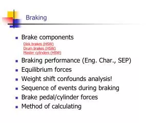
Thermal Issues in Braking. Understanding the Problem Designing brake systems to cope Pad-Disc Interface Friction Materials Brake Fluids Brake cooling Retarders. Braking Duty -Main Concerns. DUTY CONCERN City running (250-350°C) Lining and rotor wear

Thermal Issues in Braking
E N D
Presentation Transcript
Thermal Issues in Braking • Understanding the Problem • Designing brake systems to cope • Pad-Disc Interface • Friction Materials • Brake Fluids • Brake cooling • Retarders
Braking Duty -Main Concerns DUTY CONCERN • City running (250-350°C) Lining and rotor wear • Alpine Descent (600-700°C) Fade, wear, vaporisation, pedal travel • Autobahn Stops Disc cracking, hot judder • Fade test (e.g. AMS ) Fade, pedal travel
City Driving • Critical effect of temperature on brake wear • Front Spoiler can severely reduce pad life • Significant effect on service intervals and cost of ownership
Alpine Descent Temperatures • Grossglockner • Industry Standard • 10 miles • 10 % gradient • 600-700°C Discs • 150-200°C Fluid Driving Soak Front Rear Front Fluid
Autobahn Stops • Up to 300 kw initial heat input • 600-700°C Differential • Disc cracking • Hot judder (Blue spotting)
Fade – e.g. AMS Stopping distances 80 COLD 70 HOT 60 50 40 m 40 Distance (m) 30 20 10 0 M3 320i 728i A4 1.8 A6 2.6 A8 4.2 523i (E39) 535i (E39) Cuore GLX 328i (veh 1) ESPERO 1.8 Spider 2.0 TS A4 2.8 (veh 2) NEXIA 1.5 GL Alpina B8 4.6 ZX Break 1.9 TD 318ti COMPACT 75 Spider 2.0 V6 VOYAGER 2.4SE VOYAGER 3.3SE
Minimising the thermal input - Designing brake systems to cope • Avoid excessive duty on any brake • Optimising brake distribution
Braking Distribution • Commercial Vehicles • Predominance and load sensing valves • Coupling force control to spread duty levels with advent of brake by wire • Cars and light Commercials • Front brakes have high duty • Need to maximise rear braking duty
High Rear Thresholds Large differential between Front and rear axles Front Rear High rear thresholds (e.g. arising from integral PCRV in RWC) - resulting in excessive front duty Front Fluid
EBD and ZCrit(ZCrit = Decel at point of rear lock) Typical PCRV Non ABS characteristic Same system with EBD PCRV EBD x axis = deceleration, y axis = proportion of rear braking EBD failure gives rear lock @ 0.4 g System revised to give rear lock @ 0.7 g EBD Fail EBD Failure Zcrit 0.4 g EBD Failure Zcrit 0.7 g Resulting 30% Reduction in rear braking at 0.2g
Minimising Thermal Effects • Minimising brake fluid temperature – pad under-layer • Less heat into caliper gives increased lining degradation • Heat needs to go somewhere
Bucket Analogy • Flow from tap = Brake energy in • Height of Water = Rotor temp • Size of hole = cooling capability • Plan area = rotor heat capacity
Alternative Strategies • WIDE BUCKET • Large Heat Capacity • Good Cooling • Low Temperatures E.g. Aluminum MMC Discs
Alternative Strategies • WIDE BUCKET • Large Heat Capacity • Good Cooling • Low Temperatures E.g. Aluminum MMC Discs • TALL BUCKET • Small Heat Capacity • Moderate Cooling • High Temperatures • E.g. Thin solid steel or cast iron disc with plasma ceramic coating running at up to 1100°C
Methods of Determining the Rotor Size • Benchmarking against current vehicles • Single stop temperature rise calculations • Fade and Alpine descent prediction • Sizing by packaging constraints
Single Stop Temperature Rise > t < • Thickness t 2.16 cm Density 7.873 g/cc • Vent factor 0.7 Spec. Heat S 550 J/kg/°C • Diameter OD 26.2 cm Veh mass M 1910 kg • Diameter ID 16.1 cm Brake balance 80% front • Calc area 336 cm2 Max speed 230 km/h • Calc vol. 507 cc = 63.9 m/sec • Disc mass m 3994 g
Calculating Temperature Rise • K.E. = ½mV2 Total energy kinetic energy = 3898110J • Energy per front brake = 1559244J (80% shared) • Calculate temperature rise T: Energy = mSdT • Therefore temperature rise, T = 710°C Rotor Type SSTR (°C) Drum 350-400 Solid Disc 550 Vented Disc 600-650 If the above SSTR values are exceeded then in-service problems could occur
Single Stop Temperature Rise • Indication for single stop on the autobahn • Reasonable quick indicator • Empirical evidence for SSTR figure • Shortcomings • No allowance for the brake cooling • Not for an AMS test or alpine descent • Should not be relied upon for new designs
Fade and Alpine Descent Predictions • Uses increased computing power availability from PC’s and workstations • Predictions can be much more involved • Possible to calculate predicted temperatures for a fade test and Alpine descent • Better judgements at the concept stage.
Fade and Alpine Descent Predictions • Uses assumed cooling coefficients (often based on a current vehicle) • Significant changes in the brake cooling rate will not be reflected in the predictions. • Currently most effective technique
Sizing by packaging constraints • Often need to design the biggest rotor possible in the packaging space available • Method most often used in practice • Engineer’s preference • Brake rotors not often oversized • Decisions made at the concept stage for brake sizing made on optimistic assumptions
Why Maximise Rotor Size? • Weight always increases • (First prototype is always the lightest) • Subsequent versions often include estate or high performance derivatives • Customer expectations continually change • Increasing service intervals • Changing technology • e.g. reduced overrun braking on auto boxes • If the brake size is marginal, then subsequent lining choices are compromised (limited to high mu linings)
Maximising Disc Size • Wheel size tends to define rotor sizing • Wheel Types • Steel wheelsmore restrictive • Alloy wheels not normally fitted to base-line • Cold formed fabricated alloy wheels worst
Caliper clearances • Clearances • Wheel to Caliper • Caliper to disc • Caliper stiffness defined by “b” affecting: • Pedal travel • Pressure distribution • Aluminium calipers • Require greater b dimension
Pressure Distribution • Effect of uneven pressure distribution • Localised Heating • 6 stops from 80 km/h (IBT < 100°C)
Detailed disc design • Large thermal gradients cause differential expansion of the disc brake material • Thermally unstable disc is likely to induce cracking and both hot and cold judder • Energy needs to be fed into friction ring evenly • Stable disc design with minimal coning • Minimal runout and bolt-up distortion • Suitable disc material
Thermal Effects • Thermal stresses greater than mechanical stresses • Coning gives rise to • Increased pedal travel • Taper wear • Uneven heat input (risk of forming hot bands)
Disc Coning and Undercuts • Minimise stiffness of top hat and undercut
Disc Material • Thermal Stresses >> Mechanical • Maximising Thermal Conductivity • Graphite Flake Structure • High Carbon Cast Iron (Free Graphite) • Silicon,Titanium,Vanadium, Copper, Molybdenum • Ferrite and Pearlite different characteristics
Casting Perfection • The perfect material doesn’t exist • Important to understand parameters • Casting processes vary • Partnership with the right foundry essential
Brake Cooling • Critical effect on brake temperature and performance
Brake Cooling Issues • Complex air flow through wheels • Steel and alloy wheels cars and 4x4 • Wheel trims • Wind tunnel tests • Various techniques • Timing of cooling tests • Need to establish cooling before B.I.W. tooling (Testing first prototype can be too late)
Computational Fluid Dynamics • C.F.D. can be used to predict air flow • Flow around body • Flow through ventilated disc • Wheel design • CFD can be performed early in program • At stage in programmed where body in white design can still be influenced
Component Temperatures • Service Problems Include: • Brake fluid reactions with components at elevated temperatures. • Certain combinations of fluid and brake pipe can suffer adverse reactions at sustained elevated temperatures. Cu/Zn is extracted from the brake pipe and reacts with the fluid. • Reservoir platiciser reacting with brake fluid at elevated temperatures • Certain combinations of hose and fluid producing deposits in fluid • Collapsing Vacuum pipes Nylon pipes may survive elevated temperatures if carrying positive air pressure, but can collapse due to combination of internal vacuum and temperature. • Seizing Vacuum non-return valves Non-return valves can seize shut if subjected to elevated temperatures, especially in the presence of fuel • ABS sensors melting Metropolitan Police usage can generate temperatures of up to 800°C and melt ABS sensors, especially if dirt shields are not used.
Component Temperatures • Need to perform thorough hot room tests • Take great care with heat shield deletion
Summary • Need to spread heat energy between axles • Need to optimise component design and materials
Example of Improved Cooling Forced cooling of ventilated discs • Need for BMW Autosport to improve the brake cooling on M3 motor sport vehicles • Increasing engine power brought about a marked increase in braking duty • A solution was to introduce forced cooling into the vents in the front discs.
Cooling improvement • Inner race rotates at half rate of outer race • Supplementary race to force cooling air • Reduction of 80°C at Nurburgring