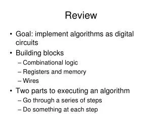
Review
Review. Card Key Access…See Kathleen Goforth Mail Archive…working on it…are you getting my messeges? Why do we connect the speaker to 5V instead of ground? Frequency range … what did you discover?

Review
E N D
Presentation Transcript
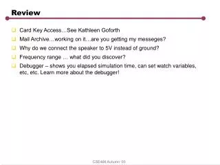
Review • Card Key Access…See Kathleen Goforth • Mail Archive…working on it…are you getting my messeges? • Why do we connect the speaker to 5V instead of ground? • Frequency range … what did you discover? • Debugger – shows you elapsed simulation time, can set watch variables, etc, etc. Learn more about the debugger! CSE466 Autumn ‘00
Simple Princeton Architecture ROM Linear Address Space W/ Mem Mapped IO I/O Port PC IR GPRs SP Timer, SFR’s RAM address Reset Vector ALU Interrupt Vect IR mux data Status Control CSE466 Autumn ‘00
Analysis • Bottleneck into and out of memory for data and code • Use of critical 8-bit address space (256) for memory mapped I/O and special function registers (timers and their controllers, interrupt controllers, serial port buffers, stack pointers, PC, etc). For example, the Motorola 6805 processor has only 187 RAM locations. • But, easy to program and debug. Compiler is simple too. CSE466 Autumn ‘00
8051: Modified Harvard Architecture PC mux address RAM SFR’s (direct) Internals Reset Vector Usually Stack (indirect) Interrupt Vect ALU Interrupt Vect Interrupt Vect 8051 standard + Enhancements (indirect or Direct) Bit Addressable Status Reg. Banks PSW – 2-bits bank sel. data instruction 3 bits reg sel ------------------ 5 bits of reg. addr Control 4x8 CSE466 Autumn ‘00
8051 Memory Architecture • Advantages • Simultaneous access to Program and Data store • Register banks great for avoiding context switching on interrupt and for code compression • 8-bit address space extended to 256+128 = 384 registers by distinguishing between direct and indirect addressing for upper 128 bytes. Good for code compression • Bit addressable great for managing status flags • Disadvantage • A little bit confusing, with potential for errors. CSE466 Autumn ‘00
Segments control address space…same in C what would you add to include an interrupt routine? NAME example PROG SEGMENT CODE CONST SEGMENT CODE VAR1 SEGMENT DATA BITVAR SEGMENT BIT STACK SEGMENT IDATA RSEG BITVAR ; relocatable segment flag: DBIT 1 ; single bit variables RSEG VAR1 ; relocatable segment ih: DS 1 ; integer i is two bytes il: DS 1 RSEG STACK ; relocatable segment DS 10H ; 16 Bytes CSEG AT 0 ; absolute segment JMP START ; Execution starts here on reset. RSEG PROG ; relocatable segment START: MOV SP,#STACK-1 ; first set Stack Pointer MOV PSW,#00 ; use register bank O ;rest of main program here CSEG AT 0BH <code> rti CSE466 Autumn ‘00
Instruction Execution • 6 States/Machine Cycle, • 2 Osc. Cycles/State = 12 Cycles/Machine Cycle • Most instructions are 1 machine cycle, some are 2 or more • Can make two ROM accesses in on memory cycle (two byte/one cycle instructions, such as ADD A,#10H. • ALE – address latch enable, used when referencing external memory which can happen twice per machine cycle. • Its a Micro-coded CISC processor (sort of an old architecture) • Interesting features • No Zero flag (test accumulator instead) • Bit operations, Bit accessible RAM • Read Modify Write operations (ports) • Register to Register Moves • Multiply and Divide operations (many 8-bit MCU’s don’t have these) • Byte and Register Exchange operations • Register banks • Data pointer registers • Addressing Modes (careful when using upper 128 bytes of RAM) • BCD oriented instructions CSE466 Autumn ‘00
Assembly Programming • Declare Segments and Segment types • Segments define what address space you are in. • Assembler converts to machine code, with relocatable segments. • Linker perform absolute code location • Segments • DATA -- Internal Data Address Space (0-7F direct or indirect) • IDATA -- Indirect Data Address Space (80-FF for stack, arrays) • Address is in R0 or R1 • BIT – Bit addressable RAM space • XDATA -- External Data Address Space • CODE – Internal or external code space • CONST – Internal or external code space • Example Assembly Program CSE466 Autumn ‘00
Last Term’s Lab1 +5V GND, VCC, XTAL, EA, Reset 8051 MCU Atmel 89C55 P1.1 +5V P2 Value on DIP switch controls LED frequency Resistor Pack CSE466 Autumn ‘00
Anatomy of an Assembly Program Look for overflow in C – difficult to do unsigned int i; void main (void) { register unsigned int tmp; while (1) { P1^= 0x01; i = 0; do { tmp = i; i += P2; } while (tmp < i); } } Note i is global and tmp is local. What happens to local variables? How are registers used? What happens in a subroutine call? CSE466 Autumn ‘00
Compiled C But, here is the optimized Compiled C ?C0001: XRL P1,#01H CLR A MOV i,A MOV i+01H,A ?C0005: MOV R7,i+01H MOV R6,i MOV R5,P2 MOV A,R5 ADD A,i+01H MOV i+01H,A CLR A ADDC A,i MOV i,A CLR C MOV A,R7 SUBB A,i+01H MOV A,R6 SUBB A,i JC ?C0005 SJMP ?C0001 CSE466 Autumn ‘00
Now in Assembly RSEG PROG ; first set Stack Pointer START: MOV SP,#STACK-1 MOV PSW,#00 ; SET TO REG BANK O CLR flag ; just for show SETB flag ; just for show LOOP1: CLR C ; Clear carry MOV A,il ; get low byte ADD A,P2 ; increment MOV il,A JNC LOOP1 ; loop until carry INC ih ; increment hi byte MOV A,ih ; check if zero JNZ LOOP1 ; XRL P1,#01H SJMP LOOP1 END NAME Lab1_00sp PUBLIC il PUBLIC ih PROG SEGMENT CODE ;CONST SEGMENT CODE VAR1 SEGMENT DATA BITVAR SEGMENT BIT STACK SEGMENT IDATA RSEG BITVAR flag: DBIT 1 RSEG VAR1 ih: DS 1 il: DS 1 RSEG STACK DS 10H ; 16 Bytes CSEG AT 0 USING 0 ; Register-Bank 0 ; Execution starts at address 0 on power-up. JMP START CSE466 Autumn ‘00
Embedded Hardware • Microcontrollers • Smallest: PIC 8-Pin (8-bit) PIC 8-pin Microcontroller • Middle: 6805 (8 bit) Example Flash Based 8051 • Many 16-bit DSP Microcontrollers • HW support for MAC, Filter Algorithms • High End: StrongArm (32 bit) Intel • Compare to pentium • External memory • Data Address Multiplexing • Memory Mapped I/O – talking to external devices • Typical Devices • Resistive Sensors (Strain, Temp, Gas, etc.) • Motion sensors (accelerometer) • Valve • Motor (Stepper, DC, Servo)\ • Speaker • LCD Display • LED • Latches • Gas Sensors CSE466 Autumn ‘00
Reset processor 1ms after powerup • 1ms = 1/32 sec ~ 31ms • Let R = 10K, so C = .031/10K = 3.1uF what is the waveform on RST? 8051 + 3.2u RST 10K - CSE466 Autumn ‘00
An output port Write Reg Pin bus CSE466 Autumn ‘00
What’s Inside the Buffer? This device always “drives” either high or low. Current is a function of pin voltage Never High Impedence ‘Z’ Ih Write Reg Il Note: this one inverts the signal, but its just an example… CSE466 Autumn ‘00
A Bi-direction Port? Write Reg Read Reg Pin bus CSE466 Autumn ‘00
I/O Ports Dir Ctl Write Reg Read Reg Pin Output driver can be disconnected from the pin so that input buffer can sense only the input signal This kind of bi-directional port requires a direction control register (SFR) for each bit of output (like StrongArm… bus CSE466 Autumn ‘00
The 8051 (always has to be different) • Eliminate the need for configuration bits by making outputs • that can only drive strongly low (sink). There are three kinds of • pins on the 8051 (of course) • No pull up • Weak pull up • Weak pull up with momentary strong pullup • To use a input pin, set output value to 1 (weak or no pullup). • External signals just have to overpower the weak pull up (low resistance to ground). • As output, will go from 0 to 1 slowly unless you add an external pullup • Data sheet doesn’t spec the resistance of the pull up, but it specs the • Amount of current that will result in a given voltage at the pin. For • Example, in Ports 1,2,3 Ioh = -25uA at .75Vcc. CSE466 Autumn ‘00
Application: Wired NOR Communication bus: Each processor tries to send data, but detects collision. If collision, then stop transmitting Collisions are safe because nobody drives high. The one who writes the zero first gets the bus! 8051 8051 8051 Q1) How can a processor detect a collision? CSE466 Autumn ‘00
Summary • Port 0: • used as address bus for external address/data bus. Uses active pullup in this mode. Fast • Can use as GPIO. Must use external pullup. Pullup size is power/speed tradeoff, up to 3.2mA • Port 1 and 3: • GPIO only. External pullups are optional. Power/speed tradeoff, up to 1.6mA. • Port 2: • Also used for external address bus. Has active and passive internal pullups. External pullups are optional in GPIO mode, up to 1.6mA. CSE466 Autumn ‘00
Example Problem 1) As big as possible! Vp Open = 0 Closed = 1 P1 R According to Data sheet: Processor reads a zero if Vpin < .2Vcc - .3 = 0.7V Ilow (port 1) is .45Vp at 50uA. So what is max R? (.45/50e-6) =9Kohms So the switch resistor better be smaller than 9Kohms. 4.7K is a good choice. 2.7 is okay but higher power! CSE466 Autumn ‘00
Careful w/ Coils (motors, etc) • Steady state on current: Vcc/R • Vds ~ 0 (Rds ~ 4mOhm) • But, when we try to turn off the • Mosfet quickly, what happens? • Rds goes up quickly, but Ids drops slowly) • If Rds becomes 1K, then Vds becomes 100V • And instantaneous power becomes 10W Current limiter R = 50Ohms I =0 .1A Coil (L) 8051 MOSFET Switch Vds CSE466 Autumn ‘00
I/O Ports • Input ports: Hi Input impedance (like CMOS transistor gate) • Output ports: Hi drive (current source/sink) capability (like CMOS transistor channel) • Bidirectional Ports? • Weak Pullup Approach used in the 8051 • Configuration bits (used in other MCU’s) CSE466 Autumn ‘00
Basic Electronics • Speaker Interface. Design a direct drive circuit for the speakers. How much power are we dissipating in the speaker if we stay within current rating of chip? • How can we get more power to the speaker? • Note to self: Saturation v. Linear operation CSE466 Autumn ‘00
Design Meeting – Speaker Driver • Problems • multiple tones • amplification CSE466 Autumn ‘00