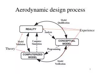
Aerodynamic Design
Aerodynamic Design. 黃俊誠 2007.10.31. Preliminary System Design. Structure. G/C. Aerodynamics vs. Gas dynamics. Aerodynamics ( 氣動力學 ) Vehicles interaction with gas flow Gas dynamics ( 氣體動力學 ) Dynamic characteristics of gas For examples Sonic Barrier Tip vortex.

Aerodynamic Design
E N D
Presentation Transcript
Aerodynamic Design 黃俊誠 2007.10.31
Preliminary System Design Structure G/C
Aerodynamics vs. Gas dynamics • Aerodynamics (氣動力學) • Vehicles interaction with gas flow • Gas dynamics (氣體動力學) • Dynamic characteristics of gas • For examples • Sonic Barrier • Tip vortex
Aerodynamic Configuration Design • Configuration
Wing Inlet Fin Nose Body
Parameters That Drive Rocket Flight Performance Stabilizer Geometry / Size Propellant / Fuel Diameter Nose Fineness Wing Geometry/Size ThrustProfile Flight Conditions ( , M, h ) Length Flight Control Geometry / Size
Aerodynamics Configuration
Nose Shape • Considerations • Minimum radar aberration • The packaging problem • Missile over all length • The structural integrity of the shape • Aerodynamic heating effects • Manufacture cost
The most common nose shapes • Conical or Bi-conic • Tangent or Secant ogival • Elliptical or Hemispherical • Power series • Parabolic series • Haack series
Conical • This shape is often chosen for its ease of manufacture, and is also often (mis)chosen for its drag characteristics.
Bi-conic • Commonly used in hypersonic vehicle, for the reason that the aerodynamic center is insensitive to wild ranges of flying Mach number and angles of attack
Tangent ogival • The popularity of this shape is largely due to the ease of constructing its profile. The nose cone length, L, must be equal to, or less than the Ogive Radius ρ. If they are equal, then the shape is a hemisphere
Secant ogival • The Ogive Radius ρ is not determined by R and L (as it is for a tangent ogive), but rather is one of the factors to be chosen to define the nose shape. • The rocket body will not be tangent to the curve of the nose at its base.
Elliptical or Hemispherical • This shape is popular in subsonic flight (such as model rocketry) due to the blunt nose and tangent base. This is not a shape normally found in professional rocketry. If R equals L, this is a hemisphere
Parabolic • This construction is similar to that of the Tangent Ogive, except that a parabola is the defining shape rather than a circle. • K’ can vary anywhere between 0 and 1, but the most common values used for nose cone shapes are: • K’ = 0 for a cone • K’ = 0.5 for a 1/2 parabola • K’ = 0.75 for a 3/4 parabola • K’ = 1 for a full parabola
Power series • The Power series nose shape is generated by rotating a parabola about its axis. • The factor n controls the ‘bluntness’ of the shape. As n decreases towards zero, the Power Series nose shape becomes increasingly blunt. • At values of n above about 0.7, the tip becomes sharp. • Where • n = 1 for a cone • n = 0.75 for a 3/4 power • n = 0.5 for a 1/2 power (parabola) • n = 0 for a cylinder
Haack series • The shapes are not constructed from geometric figures. The shapes are instead mathematically derived for the purpose of minimizing drag. • Haack nose tips do not come to a sharp point, but are slightly rounded. • Where : • C = 1/3 for LV-Haack, ‘LV’ indicates minimum drag for a given length and volume • C = 0 for LD-Haack (also known as the Von Kármán or the Von Kármán Ogive) , the notation ‘LD’ signifies minimum drag for the given length and diameter
Nose cone drag characteristics • For aircraft and rockets, below Mach 0.8, the nose pressure drag is essentially zero for all shapes. The major significant factor is friction drag, which is largely dependent upon • the wetted area, • the surface smoothness of that area, and • the presence of any discontinuities in the shape. • For example, in strictly subsonic rockets a short, blunt, smooth elliptical shape is usually best.
Nose cone drag characteristics • In the transonic region and beyond, where the pressure drag increases dramatically, the effect of nose shape on drag becomes highly significant. • The factors influencing the pressure drag are • the general shape of the nose cone, • its fineness ratio, and • its bluffness ratio.
Influence of the general shape • Comparison of drag characteristics of various nose cone shapes in the transonic regions. Rankings are: superior (1), good (2), fair (3), inferior (4).
Influence of the Fineness Ratio • The ratio of the length of a nose cone compared to its base diameter is known as the ‘Fineness Ratio’. The length/diameter relation is also often called the ‘Caliber’ of a nose cone. • At supersonic speeds, the fineness ratio has a very significant effect on nose cone wave drag, particularly at low ratios; but there is very little additional gain for ratios increasing beyond 5:1. • As the fineness ratio increases, the wetted area, and thus the skin friction component of drag, is also going to increase. Therefore the minimum drag fineness ratio is ultimately going to be a tradeoff between the decreasing wave drag and increasing friction drag.
Body Mid-Section • In general cylindrical. The advantages being that: • Only Skin friction drag is incurred • Motor case can become skin of missile • Ease of manufacturing • Good load carrying capacity
After-body Shapes • The purpose of a boat-tail is to decrease the after-body drag. • Base drag arises through flow separation behind the base. The effect of this flow separation is to bring about a reduction of the base pressure PB below the free stream value P
Wing or fin • The criteria affecting wing design are • Maximum permissible span • Required G capability incidence • Required stability • Speed and Trim angle • Structural efficiency • Minimum drag • Configuration design parameters • Wing Section • Aspect Ratio • Wing Planform
Wing Section • The airfoil shape or section for supersonic application is noticeably different from those sections used in the subsonic region.
Wing Section • In general, sharpnosed symmetrical airfoil sections of the double wedge, modified double-wedge or biconvex results in the most efficient aerodynamic design. • While a sharp leading edge is desirable from the standpoint of maintaining shock attachment, there by reducing wave drag, and adverse pressure gradient, it may be necessary to round the L.E. to minimize the aerodynamic heating effect.
Wing Section • The normal force for a sharp leading edge is higher than that for a rounded leading edge. • With a rounded leading edge the flow separation takes place aft of the separation point of a sharp leading edge, thus reducing the non-linear lift component. • In the final selection of an airfoil, one must also consider the structural efficiency and manufacturing costs as well as aerodynamic efficiency, whereas • a double wedge has the minimum drag per unit thickness, • a biconvex has lower drag/unit strength. • From a manufacture aspect modified double-wedges are easier to manufacture and are also more suitable for controls to accommodate the actuation shaft.
Aspect Ratio • The aspect ratio may be defined as • Aspect ratio = (Wing span)2/Wing area • Increasing Aspect Ratio then • Increases CN, CDo • Increases structural weight, linearity of aerodynamics • Reduces stall angle, trim angle of attack Wing span b, and area S
Aspect Ratio • Low aspect ratio surfaces are predominant in missile design studies. • The non-linearity of the aerodynamic characteristics and high stall angles associated with these surface are made use of to achieve the high maneuver accelerations.
Wing Planform • Rectangular wing is used in low speed, low incidence vehicle with the advantage of low cost and good area effects. • If we need more lift, but the area or span is restricted, and there is no advantage of increasing chord length at low incidence, then what is the wing planform we needed. • At subsonic speed, the highly swept delta surface has a high non-linear lift coefficient due to L.E. separation. The stall occurs at high incidences.
Wing Planform • At supersonic speeds, the choice will be dependent upon the missile speed and maximum incidence and the design constraints of geometry. • For a constant span restriction, the effect of chord at low incidence is insignificant. At higher incidences the effect of chord becomes more predominant as the area effects on the nonlinear term becomes important. • There is a significant advantage in going to a rectangular or cropped delta planform. It is preferable from lift point of view to increase taper ratio rather than chord if a span restriction is placed on the designs.
Wing Planform • The advantages to be gained from cropping, however, may be offset by the increase in wing mass, wave drag, and the increase in the movement of centre of pressure possition. • It has been investigated that for a given wing span the double delta wing has an advantage from normal force point of view over the straight-tapered and delta wing.
Aerodynamics Fluid Flow
Real fluid flow about an airfoil • Thickness of boundary layers and wake greatly exaggerated
Dependence of flow on Reynolds number. • Re = ( Vl)/µ • density of fluid, kg/m3 • V mean velocity of fluid, m/sec • l characteristic length, m • µ coefficient of viscosity (called simply "viscosity" in the earlier discussion), kg/m-sec
Surface roughness and flow field. • All cases at same Reynolds number
Force & Moment Coefficients • Lift coefficient • Drag coefficient • Coefficient of moment
Drag coefficients and Reynolds number • At supercritical Reynolds numbers from 106 and larger, the laminar boundary layer becomes turbulent and separation is delayed; hence, the smaller CD values. A rather abrupt transition occurs between Reynolds numbers of 105 and 106. These values are the critical Reynolds numbers.
Aerodynamics Fluid Flow Subsonic Flow