Download
1 / 40
400 likes | 547 Vues
POWER LEVEL MONITORING DEVICE FOR GMRT RECEIVER. SURJYA NEOGY INSTITUTE OF RADIOPHYSICS & ELECTRONICS. Purpose. Initial Requirement : To Monitor Power Level at Various Stages of GMRT Receiver Chain

E N D
POWER LEVEL MONITORING DEVICE FOR GMRT RECEIVER SURJYA NEOGY INSTITUTE OF RADIOPHYSICS & ELECTRONICS
Purpose • Initial Requirement : To Monitor Power Level at Various Stages of GMRT Receiver Chain • Project Extension : Upgrade Power to Monitor by Designing Necessary Interface to General Purpose Power Meter.
Content • GMRT • RF Power Detection • Operation • Construction • Voltage Conditioning Circuit 5. Instruments & GMRT Module • Front End Simulator 6. Characterization & Calibration 7. Antenna Base Measurements • Project Extension: General Purpose Power Meter • DPM Interfacing • ADC Interfacing 9. Summery & Further Extension 10. Reference
1.GMRT • Rotateable Feeds for 150 MHz–610 MHz & L-band • Front End Systems with LNA & Filters at the Dish Base. Two Channels • IF – Base band – LO Loop down conversion of RF Frequencies to 175 MHz & 130 MHz. • Optical Fiber Transmission to CEB, again up conversion of frequency • Correlate Signals at Correlator System. • Remote MCM
2.RF Power Detection • Main Component LT5534 • Logarithmic Amplifier • Cascaded RF detector & RF Limiters to produce 60 dB of Dynamic Range • Low Output Impedance Driver buffer at the output • Tolerate Large variation operating Temperature
3.Operation • Connect dc Supply • Connect the RF Input • Wait till Stabilization • Make RS-232 Interface with PC • Run “mcmprnn .exe” from Command Prompt • Check 04-01 Matrix Element on the console
Detector Prototype RF signal port is DC blocked Resistance connected to output provides improved matching Compensating Capacitor ensures stable operation Output currents from RF Detector are summed up and converted into output voltage The circuit & PCB Layout is shown in next slides. Detector Module Directional Coupler PDC-10-5 is used to bypass required amount of signal to Detector Input This introduces additional 10 dB of loss so that power level goes bellow -50dBm. Amplifier MAR-6+ is employed to boost the signal strength LM 7805 is used as Power Supply 4.Construction
Voltage Conditioning Circuit • Detector Output is not compatible with MCM • To ensure usage of full Dynamic Range Voltage Conditioning Circuit is needed • A simple Differential Amplifier Circuit • To avoid serious Loading Problem in IC741, a buffer is also used. • The Output of It is get connected directly to the RS-232 Connection Cable
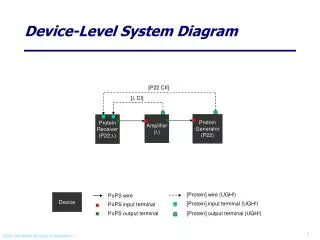
5.Instrument & GMRT Module • To characterize the power detector many instruments are used, among them the most important instruments are discussed in brief • The Monitoring & Control Module (MCM) and the Front End Simulator Module (FE Simulator) are also used frequently. Among them, to get desired broad band noise the FE Simulator Module is slightly modified. These two modules are also discussed here.
Boonton 4232A Dual Channel, GPIB, 10 KHz to 100 GHz RF Power Meter
Monitoring & Control Module (MCM) of GMRT • MCM is a general purpose Micro-controller based card • Antenna Computers communicate with MCM through RS-485 cable and sets various FE, LO and IF system parameters and also monitor the ABR parameters • The C44 PIU no. 116 MCM is used in this project
Front End Simulator • A wideband noise generator is used to develop the FE system simulator • This simulator is used to simulate 150MHz, 235MHz, 325MHz and 610MHz FE outputs • In this system a wide band noise source using NC-501 is used to generate the noise which is further amplified and passed through a filter bank to generate the noise • Data are taken to find extreme Power Level Output.
Design of LPF • To boost up its output power level an IF amplifier is used just before the power divider. • The out of band noise form the simulator is getting more prominent for the lower power levels. • To suppress this unwanted out of band disturbances, A Low Pass filter of cutoff frequency of 800MHz is also employed between the Noise Generator and the Filter Bank. • The modified block diagram of the FE Simulator is shown in the next page
6.Characterization & Calibration • Every newly designed system should be thoroughly characterized and perfectly calibrated using some predefined instruments. The instruments mentioned earlier are extensively used in these purposes. • The characterization part is done mainly using the R&S Spectrum Analyzer and Boonton Power meter is used for final calibration of the system. • A large number of measurements are done with both the detector prototype as well as detector system; among those the most important results are included here. Most of the plots are included while in each case only one sample datasheet is provided and the rests are available as datasheet.
7.Antenna Base Measurements • This detector module is to be installed at the Front End of the ABR as shown by the arrow in the figure Below. • The monitor suffers an extra RF cable loss as compared with the Front End receiver
8.Project Extension:General Purpose Power Meter • DPM Interfacing :The DPM interfacing is necessary for any general purpose power meter to display the input power directly on the Digital Panel Meter (DPM). • ADC Interfacing :The ADC Interfacing is necessary to have the facility of displaying the power level onto any Personal Computer console, to store data in removable media and to manipulate data for further signal processing.
DPM Interfacing • The DPM has an input voltage range of 1999 unit corresponding to that there is 1999 count at its display DPM interfacing is to scale the output voltage of the detector with the DPM counts • This circuit is a level shifting circuit using OP-AMP • This is capable to shift the DC output voltage level of the detector module in accordance with the calibrated power level
ADC Interfacing • The heart of this ADC interfacing is IC MAX132(15) , a CMOS, 18-bit plus sign, serial-output ADC. • An RS-232 port has three output lines. Pin3 (TX), Pin 4 (DTR) and Pin 7 (RTS), TX generates the clock signal for the MAX-132 and provides the negative power supply, DTR transmits serial data and RTS provides the CS signal and the positive power supply. • For data acquisition and to display it onto console a small screen display routine is developed in C language.
9.Summery & Further Extension • With proper schedules and planning, the project is completed within the stipulated time. After integration of power monitor and later the power meter it is checked for proper operation in the lab environment as well as in the ABR. The instrument is also thoroughly calibrated and characterized. At the end it can be concluded that the detector device is working satisfactorily. • There is still some nominal job is remaining to finish up the whole module. They are listed bellow: • The voltage conditioning circuit is made temporarily for testing purpose. It is yet to be finished. • The ADC interfacing routine can be modified to get the facilities of data storage and signal processing. • The outer chassis of the power meter is yet to be built. • The power monitor should be tested for other two or three antennas. • While designing the differential amplifier, there was incident of loading problem, so an extra OPAMP is used. Care should be taken to redesign the circuit with minimum number of active device. • For the lower power level, e.g. bellow -60 dBm, the characteristics curve remains no longer straight line. So to measure the power level of -60 dBm, a lookup table can be incorporated which is expected to be program driven. • If time is allotted in solving these shortcomings the power monitor and the power detector can be demanded successful.
10.Reference I • (1)http://www.gmrt.ncra.tifr.res.in/ • (2)Edited by J.N. Chengalur, Y. Gupta, K.S. Dwarakanath • “Low Frequency Radio Astronomy” • GMRT-NCRA-TIFR • (3) http://www.linear.com/pc/productDetail.do?navId=H0,C1,C1011,C1743,P2489 • (4)Ref. Logarithmic Amplifier AD-8307 • http://www.analog.com/en/prod/0%2C2877%2CAD8307%2C00.html • (5)Adoni, A. B. • “Design of differential amplifier on MCM card” • National Centre for Radio Astrophysics, 1992 Aug. 21st, 2 p. (090237) • http://www.gmrt.ncra.tifr.res.in/~lib/gmrt/techrep/fullt/90237.pdf • (6)http://www.labx.com/v2/spiderdealer2/vistaSearchDetails.cfm?LVid=3160356 • (7)http://www.testequity.com/products/783/ • (8)http://www.valuetronics.com/Details.aspx?ProdID=1238&Model=Agilent%20H • P_8714C • (9)http://www.eurekaspot.com/search/compare.cfm/RFPWRM/BON/4232A.html
10.Reference II • (10)http://www.gmrt.ncra.tifr.res.in/gmrt_hpage/sub_system/mcm/mcm.html • (11)Chillal, K, Ajith Kumar, B. • “FE simulator for tests on IF system” • 2000 April 18th, 9 p.(R00174) • http://www.gmrt.ncra.tifr.res.in/~lib/gmrt/techrep/fullt/R00174.pdf • (12)Arthur Williams, Fred J. Taylor • “Electronic Filter Design Handbook” • McGraw-Hill Handbooks, Fourth Edition • (13)http://www.gmrt.ncra.tifr.res.in/gmrt_hpage/sub_system/front/front.html • (14)Ram Gayakwa • “OpAmpsand Linear Integrated Circuits” • C.H.I.P.S. Fourth Edition • (15)http://www.maxim-ic.com/quick_view2.cfm/qv_pk/1347 • (16)http://www.edn.com/article/CA159691.html?spacedesc=designideas&indus • tryid=44217 • (17)Axelson, Jan • “Serial Port Complete: Programming and Circuits for RS-232 and RS-485 • Links and Networks” • Lakeview Research
Thank You Thank You All for Your Patient Hearing