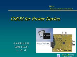
CMOS for Power Device
2004-1 Microwave Device Term Project. CMOS for Power Device. 전파공학 연구실 2003-21576 노 영 우. Outline. RF Performance of CMOS. RF CMOS Modeling. Problem of CMOS for Power device. Power performance of CMOS. Solution for CMOS Power Amplifier. Conclusion. RF CMOS is optional

CMOS for Power Device
E N D
Presentation Transcript
2004-1 Microwave Device Term Project CMOS for Power Device 전파공학 연구실 2003-21576 노 영 우
Outline • RF Performance of CMOS • RF CMOS Modeling • Problem of CMOS for Power device • Power performance of CMOS • Solution for CMOS Power Amplifier • Conclusion
RF CMOS is optional • Much work • Sufficient design enviroment • RF CMOS Tech. Inductor, MIM, Varactor • How many product ! • No commercial • Handle design for CMOS RF/Analog/Digital chip • Much work for CMOS PA Integration • RF CMOS ? • Few works in Device modeling • Insufficient design environment • Digital CMOS Tech. • Most work from Univ. • CMOS PA (Study) • Only LDMOS , BV > 20V • Essential for low cost product • Provide design kit • model, layout DB • Deep well tech. • GSM phone (Si-lab) • 1.8 V/ 3.3 V & Circuit • below 200 mW is common Expectation of CMOS limit always changes with time - Enormous research, investment, engineers, foundry………. View of RF CMOS for System on a Chip 5~6 years ago 2~3 years ago Today
RF performance of CMOS RF performance of Active Device Performance • 0.18 CMOS shows 150 GHz fmax • 0.05 um SOI of CMOS - fT of 178 GHz - fmax of 193 GHz • Comparable with SiGe HBT Technology - fmax of 240 GHz Ref. : L. F. Tiemeijer, et al., ’01 IEDM, Secession 10-4 S. Narasimha, et al., ’01 IEDM, Secession 29-2
RF performance of CMOS Device Performance with Scale-down Fmax & Noise of CMOS Inductor Q, linearity • Gm increase : improve fmax, Fmin, IP3 • Metal layer increase : improve inductor Q Ref. : SIA The national Technology Roadmap for Semiconductors, 1998 E.Moriuji, et al., Sysm. On VLSI Circuits, 1999
RF performance of CMOS Noise performance NMOSFET vs PMOSFET • Two times lower fmax, fT compared with NMOSFET because of mobility (Transconductance) Ref. : C. S. Kim, et al., EDL, pp 607-609, Dec.2000
RF CMOS Modeling • For successful RF circuit design, the proper prediction of Frequency characteristics (fT, fmax) Small signal modeling Linearity characteristics (P1dB, IP3) Large signal modeling Noise characteristics (NF, Rn) Noise modeling are required. Basic CMOS model for RF Limit of SPICE Model (BSIM3v3) UC Berkeley Model Limit in High freq. For Digital, low freq Analog Circuit Need Rg for S11, Rsub for S22
What is the market asking for ? Distributed Active Transformer
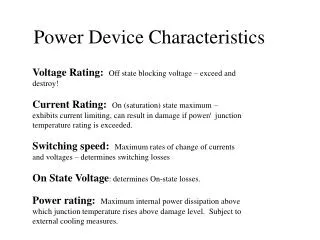
Problem of CMOS for PA Unsuitable Device for PA ( High Knee Voltage ) For high efficiency, Vknee should be low, Vmax should be high (~BVdss ~ 2VDD)
Problem of CMOS for PA Unsuitable Device for PA ( Large Voltage Swing ) Load line for Pin=25 dBm ~ 2Vdd BVdss of LDMOS ~ 20V, Unsuitable for integration Oxide breakdoun limit Hot carrier effect Reliability limit Excellent potential for 2~5 GHz wireless comm.
Problem of CMOS for PA Effect of Scaling on the Design of CMOS PA As minimum channel length Lmin of MOS Tr scales down, Reduced supply voltage ( 3.3 V for 0.35 um & 2.5 V for 0.25 um ) Required load resistance to be reduced The smaller load resistance required for a down scaled CMOS technology results in larger power loss in the impedance matching network lower efficiency “1 W still remains a challenge !”
Power performance of CMOS 800 ~ 900 MHz 1700 ~ 1900 MHz
Power performance of CMOS 2.4 GHz 5 ~ 5.3 GHz
Power performance for Wfinger Device Size Load pull measurement • VDD = 3.0 V • Thick Oxide, L= 0.35 um • Current 22 mA
Load Pull Measurement of Power Transistor Thick Oxide power transistor using 0.25 um @ 2 GHz @ 5 GHz • VDD = 3.0 V • Thick Oxide, L= 0.35 um
Solutions for Large Swing (Case 1) Thick Gate Oxide in 0.2 um CMOS ( Timothy C. Kuo, Philips, ISSCC’01 • A 1.5W Class F RF PA in 0.2 um CMOS • By using Thick Ox. : output node sustain 7 Vp <Cascode Topology> • Sine wave driver VS square wave driver • Inductor tuning driver: Negative swing damage oxide • Higher efficiency in square driver case
Solutions for Large Swing (Case 1) Inverter Driven 2-stg Power Amplifier in 0.2 um CMOS • Class F: Resonate Co & Lo @ 2fo • Power control: Control the cascode bias • Class D, E (switching PA) : BVdss > 3.6 VDD • VDD (3V/1.8V), 900 MHz, 1.5W, PAE(43%), Class F
Solutions for Large Swing (Case 2) Self-biased Cascode 0.18 um CMOS ( Tirdad Sowlati, Philips, ISSCC’02 ) • DC of D2 and G2 : same • Bias for G2 is provided by Rb /Cb • Rb /Cb is chosen for Equal gate-drain signal swing on M1 and M2
Solutions for Large Swing (Case 2) Self-biased Cascode 0.18 um CMOS ( Tirdad Sowlati, Philips, ISSCC’02 ) • Inter stage LC, Output MN (off chip) • VDD=2.4 V, Po= 23.5 dBm, PAE(45%), Gain 38 dB • Hot carrier degradation @ 23.5 dBm (6 days) 23.4 dBm
5 GHz CMOS Power Amplifier (Case 3) 802.11a WLAN ( David Su, Atheros, ISSCC’02 ) • Fully differential Class A • 0.25 um CMOS, 3.3 V, 190 mA • 22 dBm
Highly linear PA for OFDM Single power supply 3.3 V Small size package with heat sink Multi-Band/ Mode CMOS PA Dual Band PA ( WLAN Application )
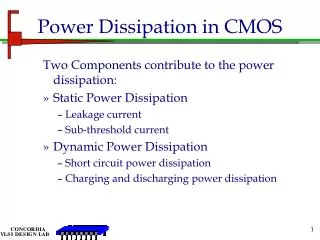
Conclusion • CMOS is most unsuitable device for power amplifier, but much works to integrate the PA will be continue. • Good performance RFIC ~ Good active device design • Library is not sufficient for high performance IC design. • 802.11 a/b/g low power, multi-band, multi-mode PA application - High integration level