Power Management for CMOS Systems
240 likes | 476 Vues
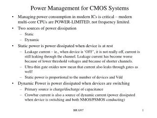
Power Management for CMOS Systems. Managing power consumption in modern ICs is critical – modern multi-core CPUs are POWER-LIMITED, not frequency limited. Two sources of power dissipation Static Dynamic Static power is power dissipated when device is at rest

Power Management for CMOS Systems
E N D
Presentation Transcript
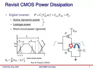
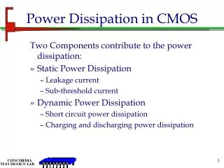
Power Management for CMOS Systems • Managing power consumption in modern ICs is critical – modern multi-core CPUs are POWER-LIMITED, not frequency limited. • Two sources of power dissipation • Static • Dynamic • Static power is power dissipated when device is at rest • Leakage current – ie., when device is ‘OFF’, it is not really off, current is still leaking through the channel. Leakage current has become worse because of lower threshold voltages and because of shorter channels. • Ultra-thin gate oxides now mean that current also leaks through gates as well! • Static power is proportional to the number of devices and Vdd • Dynamic Power is power dissipated when devices are switching • Primary source is charge/discharge of capacitance • Crowbar current is also a source of dynamic current (power dissipated when device is switching and both NMOS/PSMOS conducting) BR 6/07
Dynamic Power • Dynamic power is required to charge and discharge load capacitances when transistors switch. • One cycle involves a rising and falling output. • On rising output, charge Q = CVDD is required • On falling output, charge is dumped to GND • This repeats Tfsw times over an interval of T Source: David Harrison BR 6/07
Dynamic Power Cont. Key equation for dynamic power BR 6/07 Source: David Harrison
Activity Factor • Suppose the system clock frequency = f • Let fsw = af, where a = activity factor • If the signal is a clock, a = 1 • If the signal switches once per cycle, a = ½ • Dynamic gates (ie., domino logic): • Switch either 0 or 2 times per cycle, a = ½ • Static gates: • Depends on design, but typically a = 0.1 • Dynamic power: BR 6/07 Source: David Harrison
Short Circuit Current (Crowbar Current) • When transistors switch, both nMOS and pMOS networks may be momentarily ON at once • Leads to a blip of “short circuit” current. • < 10% of dynamic power if rise/fall times are comparable for input and output Source: David Harrison BR 6/07
Example • 200 Mtransistor chip • 20M logic transistors • Average width: 12 l • 180M memory transistors • Average width: 4 l • 1.2 V 100 nm process • Cg = 2 fF/mm Source: David Harrison BR 6/07
Dynamic Example • Static CMOS logic gates: activity factor = 0.1 • Memory arrays: activity factor = 0.05 (many banks!) • Estimate dynamic power consumption per MHz. Neglect wire capacitance and short-circuit current. Source: David Harrison BR 6/07
Dynamic Example • Static CMOS logic gates: activity factor = 0.1 • Memory arrays: activity factor = 0.05 (many banks!) • Estimate dynamic power consumption per MHz. Neglect wire capacitance. Source: David Harrison BR 6/07
Static Power • Static power is consumed even when chip is quiescent. • Ratioed circuits burn power in fight between ON transistors • Leakage draws power from nominally OFF devices Source: David Harrison BR 6/07
Ratio Example • The chip contains a 32 word x 48 bit ROM • Uses pseudo-nMOS decoder and bitline pullups • On average, one wordline and 24 bitlines are high • Find static power drawn by the ROM • b = 75 mA/V2 • Vtp = -0.4V Recall that pseudo-NMOS dissipates static power when output is low! Source: David Harrison BR 6/07
Ratio Example • The chip contains a 32 word x 48 bit ROM • Uses pseudo-nMOS decoder and bitline pullups • On average, one wordline and 24 bitlines are high • Find static power drawn by the ROM • b = 75 mA/V2 • Vtp = -0.4V • Solution: Saturation current of pullup 24 of 48 bitlines are low 31 of 32 decoder output lines low Source: David Harrison BR 6/07
Leakage Example • The process has two threshold voltages and two oxide thicknesses. • Subthreshold leakage: • 20 nA/mm for low Vt • 0.02 nA/mm for high Vt • Gate leakage: • 3 nA/mm for thin oxide • 0.002 nA/mm for thick oxide • Memories use low-leakage transistors everywhere • Gates use low-leakage transistors on 80% of logic Source: David Harrison BR 6/07
Leakage Example Cont. logic • Estimate static power: • High leakage: • Low leakage: • If no low leakage devices, Pstatic = 749 mW (!) memory gate leakage half of the transistors are leaking (subthreshold) Total gate length of high leak, low leak transistors Source: David Harrison BR 6/07
Low Power Design • Reduce dynamic power • a (activity factor) : clock gating, sleep mode • C: small transistors (esp. on clock), short wires • VDD: lowest suitable voltage • f: lowest suitable frequency • Reduce static power • Selectively use ratioed circuits • Selectively use low Vt devices • Leakage reduction: stacked devices, body bias, low temperature Source: David Harrison BR 6/07
Sleep Mode/Power down Modes in Intel Dual-Core Xeon Cache System (65 nm) Block select on during normal operation , shorting virtual VSS to real VSS BR 6/07
Sleep Mode/Power down Modes in Intel Dual-Core Xeon Cache System (65 nm) Block select OFF during sleep, Virtual VSS raised by 250 mv, logic state retained BR 6/07
Sleep Mode/Power down Modes in Intel Dual-Core Xeon Cache System (65 nm) Block select OFF, Shut-off transistor OFF during shut-off mode, raising virtual VSS by 500 mv, logic state is not retained. BR 6/07
Long Channel vs. Nominal length Channel transistors Long channel transistor is about 10% longer than nominal length Reduces drive strength by about 10% (and hence increases delay) But leakage is reduced by 3X! Any timing path with slack uses long channel transistors. Usage map across die. Caches uses about 100% low-leakage transistors, cores 54%, and IO logic 76%. Intel Dual-Core Xeon (65 nm) BR 6/07
Power Map Lower voltage used in L3 cache (1.10) Higher voltage in Cores If cache did not use low leakage transistors, then this percentage would be much higher because number of transistors in cache greatly outnumber the core transistors. Intel Dual-Core Xeon (65 nm) BR 6/07
Other ways to control Leakage • Some processes offer versions of ‘low-leakage’ transistors in which the gate-oxide thickness is increased • Thicker Gate Oxide increases Vt • Reduces gate to substrate leakage by orders of magnitude • Reduces channel leakage by 10-100 x • Increases delay by 5-20% • In twin-tub processes or Silicon-on-insulator, can adjust substrate voltage dynamically to increase Vt • For NMOS (P-Well), connect P-well to a negative voltage to increase Vt • For PMOS (N-Well), connect N-well to a higher supply voltage than the normal VDD supply BR 6/07
Dynamic Voltage/Clock Scaling Dynamic voltage and frequency management for a low-power embedded microprocessorNakai, M.; Akui, S.; Seno, K.; Meguro, T.; Seki, T.; Kondo, T.; Hashiguchi, A.; Kawahara, H.; Kumano, K.; Shimura, M.;Solid-State Circuits, IEEE Journal ofVolume 40, Issue 1, Jan. 2005 Page(s):28 - 35 Digital Object Identifier 10.1109/JSSC.2004.838021 For embedded processors in mobile devices, can dynamically scale both voltage and clock frequency depending on application BR 6/07
PDA CPU Voltage dynamically scaled from 0.9 to 1.6V in 5mV steps. Frequency scaled from 8 MHz to 123 MHz in 0.5 MHz steps. PDA application chooses clock frequency, and minimum supply voltage automatically adjusted to supply that frequency BR 6/07
PDA CPU die Processor was 100% standard cell + static memory blocks BR 6/07