Photoresist
Photoresist. Edited by Sun Hyun, Choi. • Polysilicon creation. Manufacturing process of a semiconductor (1). • Wafer slicing. • Lapping & polishing. • Design for circuit. • Manufacturing a mask - pattern preparation. • Oxidation layering. • Photoresist coating. • Stepper exposure.

Photoresist
E N D
Presentation Transcript
Photoresist Edited by Sun Hyun, Choi
• Polysilicon creation Manufacturing process of a semiconductor (1) • Wafer slicing • Lapping & polishing • Design for circuit • Manufacturing a mask - pattern preparation • Oxidation layering • Photoresist coating • Stepper exposure • Develop & bake • Etching
• Ion implant Manufacturing process of a semiconductor (2) • Chemical vapor deposition • Metal deposition • Electric die sorting • Sawing • Die attach • Wire bonding • Molding • Final test •
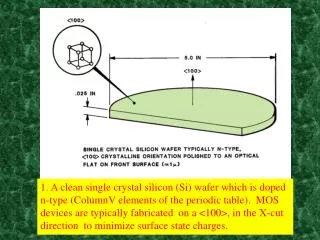
Photolithography 1 Photolithography is the sequence of activities needed for transfer a pre-designed pattern to the surface of a semiconductor wafer. The pattern can be registered on a mask, or supplied directly from a computer to a scanning radiation source. Photoresist is a photo-sensitive resistant coating used to register an image on the desired surface
Initial Viscosity: 5 to 100 cP Solvent Mass Fraction (SMF): 70-90% Photoresist viscosity for the experiments presented: 560 Resist - 17 cP 500 Resist - 40 cP Typical Viscosity Changes: 0.01 to 10,000 Poise as SMF goes from 1.0 to 0.0 Typical Diffusivity Changes: 10-6 to 10-12 cm2/sec as SMF goes from 1.0 to 0.0 Properties of Photoresist
Creation of integrated circuits, which are a major component in computer technology An extension of photolithography processes are used to create standard semiconductor chips Play a key role in the production of technically demanding components of advanced microsensors One such company is MEMS – Microelectromechanical systems Used to make adhesives in electronics Motivation
In photolithography, the pattern is created photographically on a substrate (silicon wafer) Photolithography is a binary pattern transfer: there is no gray-scale, color, nor depth to the image This pattern can be used as a resist to substrate etchant, or a mold, and other forms of design processes The steps involved are wafer cleaning, photoresist application, soft baking, mask alignment, and exposure and development Photolithography
Prepare the substrate (silicon wafer): Wash with appropriate solvent to remove any dirt and other impurities Acetone, MeOH, TCE Dry in Oven at 150°C for 10 min. Place on hotplate and cover with petri dish, let temp. stabilize at 115°C. Deposit Primer (optional) Chemical that coats the substrate and allows for better adhesion of the resist Preparation and Priming
Spin-coat the photoresist onto the surface of the wafer RPM: 1000-7000 Time: ~30 sec Produces a thin uniform layer of photoresist on the wafer surface. Use red/amber safe light at this stage Spin-Coating the Resist
Photoresist is an organic polymer which changes its chemical structure when exposed to ultraviolet light. It contains a light-sensitive substance whose properties allow image transfer onto a printed circuit board. There are two types of photoresist: positive and negative Photoresist
Two Types of Photoresist Positive Photoresist Negative Photoresist • Exposure to UV light causes the resist to polymerize, and thus be more difficult to dissolve • Developer removes the unexposed resist • This is like a photographic negative of the pattern • Exposure to UV light makes it more soluble in the developer • Exposed resist is washed away by developer so that the unexposed substrate remains • Results in an exact copy of the original design
Put on hotplate, or in oven Temperature: 65°C-115°C, Time: 1-5 min Removes volatile solvents from the coating Makes photoresist imageable Hardens to amorphous solid Be careful not to overbake and destroy the sensitizer Soft-Baking
Photomask is a square glass plate with a patterned emulsion of metal film on one side After alignment, the photoresist is exposed to UV light Three primary exposure methods: contact, proximity, and projection Mask Alignment and Exposure
Photoresist Developer • Highly pure buffered alkaline solution • Removes proper layer of photoresist upon contact or immersion • Degree of exposure affects the resolution curves of the resist
Final step in the photolithographic process Not always necessary; depends on the resist Hardens the photoresist Improves adhesion of the photoresist to the wafer surface Hard Baking
Photoresist Components Main components for lithographic capability: • Polymer (resin) - not opaque • PAC/PAG - Photo Active Compound/Group at • Solvent - compatible • Additives Capability for further process: • Etch sensitivity/Implant blocking capability.
Photo Activity Photospeeds of recording process Process ASA speedDose Resolution (ergs/cm2)-1(ergs/cm2)(lines/mm) TV tube 10410-4 5 B&W film10210-2 50 Xerox 11 100 Photoresists10-5105 5000
Photo Activity - examples • Photo synthesis Quinon x; Citicrom C, Chlorophyll. • Quinon-pigment Pigments are chemical compounds that reflect only certain wavelengths of visible light. This makes them appear "colorful". Flowers, corals, and even animal skin contain pigments which give them their colors. More important than their reflection of light is the ability of pigments to absorb certain wavelengths.
Photoresist Components Lithography generations: • g-line/Hg lamp 456 nm • i-Line/Hg lamp 365 nm • DUV/Hg lamp 248 nm • DUV/Laser 248 nm • DUV/Laser 193 nm Polymer requirement - not opaque : • Novolak is opaque at 248nm ==> use PHS • PHS is opaque at 193nm ==> use aliphatic • Aliphatic etch too fast ==> use alicyclic compounds
Dissolution inhibition chemistry. One-step chemistry during exposure. Chemical Reaction 1 Novolac / DNQ: Polymer /Resin Novolac m-cresol PAC 2,1,5-diazo naphtho quinon inden-3- carboxylic acid DNQ undergoes Wolf rearrangement
Chemical Reaction 2 CAR - Chemically Amplified Resist • Two-steps chemistry; dissolution inhibition. • PAG – triphenylsulfonium salt • Polymer/Resin PHS - polyhydroxystyrene Exposure PEB
Chemical Reaction 3 • Chemically Amplified Resist • Exposure: • PAG irradiation forms acid at exposed areas. • PEB - Post Expose Bake: • Acid react with tBOC-PHS to form soluble • PHS + acid; chain reaction/amplification. • Acid diffuses into the unexposed area. • Chain reaction stops at end of PEB process. • Resist base will neutralize the acid • Resulting line width - • smaller than optically printed.
(1) Bisazide crosslinking (2)Poly(vinyl cinnamate) (3) Novolaks (4) Diazonaphthaquione containing acrylic or styrenic polymer (5) Chemically amplified photoresists Examples of Photoresists
The earliest photoresist Based on the photo-crosslinking of “cyclized rubber” using an additive that contains two azide groups. Cyclized rubber is obtained by acid treatment of poly(cis-isoprene), which leads to some ring formation in the polymer & stiffens it (raising Tg). Bisazide Crosslinking 1
When photolyzed, the bis-azide extrudes nitrogen & produces two very reactive nitrene moieties. The nitrenes form bonds with the cyclized rubber leading to crosslinking of the polymer which becomes less soluble, ready for negative development. Bisazide Crosslinking 2 + + hv aziridine ring formation
Negative tone photoresist Synthesized by the partial esterification of poly(vinyl alcohol) with cinnamoylchloride Poly(vinyl cinnamate) 1 formed by hydrolysis of poly(vinyl acetate)
When irradiated, the cinnamate groups undergo [2+2] cyclo-addition leading to a crosslinked polymer suitable as a negative tone photoresist. Poly(vinyl cinnamate) 2 hv +
“Workhorse” photoresist of modern microelectronic revolution Phenol-formaldehyde type polymers with polycondensation reaction halted before the polymer becomes crosslinked. Novolaks 1 Novolak
Generally using cresol (methylphenol) rather than phenol. These polymers are soluble in aqueous base but the rate of dissolution is quite low. In the presence of additives, i.e. diazonaphthaquinone, the dissolution process can be greatly enhanced. Novolaks 2
When irradiated, the diazonaphthaquinone undergoes the photochemical Wolf rearrangement, producing a carboxylic acid. Novolaks 3 hv -N2 +H2O Diazonaphthaquinone additive
The acid is very soluble in base and enhances the rate of dissolution of Novolak by orders of magnitude. The un-irradiated regions are effectively insoluble leading to a positive tone photoresist. The exact reason for the increased dissolution rate is not yet understood. Novolaks 4
Same as above, on exposure to light, diazoketone group rearrange to ketenes which hydrolyze to carboxylate groups Diazonaphthaquinone containing Acrylic or Styrenic polymer NaOH (aq)
Concept: exposure to light creates a catalyst for a chemical reaction which is responsible for the change in solubility of polymer Merit: one photon can lead to many secondary reactions (very efficient) Example: poly(t-Boc styrene)-polymer contains phenolic groups protected with t-Boc groups Chemically Amplified Photoresists 1
In the presence of acid catalyst, the protecting groups decompose to carbon dioxide and isobutylene. The deprotected phenolic moieties are soluble in aqueous base. this material can function as a negative tone photoresist Chemically Amplified Photoresists 2
The unmodified polymer is soluble in non-polar solvent i.e. anisole. it can also work as a positive tone photoresist Photochemical acid generator, iodonium (R2I-X+) or sulfonium (R3S+X-) salts is added as an additive. Upon light exposure, these compounds decompose into a complicated mixture of products, chief among which is the acid HX. Very fine structure can be fabricated using this system, with very little light required to do the job. Chemically Amplified Photoresists 3
Positive Resist Processing UV Light • The layer of resist is exposed in specific areas through a mask. • Development washes away exposed resist. • In the additive process, material is deposited through the holes in the resist. • For a subtractive process, material is removed by ion milling through the holes in the resist. • In the final step, resist is removed. mask photoresist Exposure substrate Developing Deposition Ion Milling Additive Subtractive Finished Product Finished Product
Negative Resist Processing • The layer of resist is exposed in specific areas through a mask. • Baking helps to harden the exposed resist. • A second exposure exposes the soft resist. • Development washes away soft resist. • Resist remains in the areas initially exposed through the mask. UV Light mask photoresist Exposure substrate Baking 2nd Exposure Developing
Photoresist Cure PDMS, remove elastomer mask from master Si Photolithography Expose through elastomer mask RIE PDMS casting Develop PDMS Phase Mask Process Ref: H. Jiang et al., Spring MRS Meeting ‘99
Process Sequence 1) Clean wafer surface • bake (get rid of H2O) • RCA clean • apply adhesion promoter (HMDS = “hexi-methyl-di-silizane”) 2) Deposit photoresist (usually by spin-coating) 3) Soft bake (or “pre-bake”) - removes solvents from liquid photoresist 4) Exposure (pattern transfer) 5) Development - remove soluble photoresist 6) Post bake (or “hard bake”) - desensitizes remaining photoresist to light 7) Resist removal (“stripping”)
Standard photoresist chemicals Resin (e.g. Cresol-formaldehyde {Novolac} ) Solvents Ethyl lactate (EL) (b.p 154C) Ethyl 3-ethoxypropionate (EEP) Cellosolve Acetate Photo-active Compounds Developer Edge Bead Remover Solvents Chemical Usage in the Photolithography Process
Reference 1. D. Birkett, J. Chem. Ed., 2002, 79, 1081. 2. D. Bradley, Chem. Br., 2001, 37, 28. 3. Journal of Non-Crystalline Solids, Volume 352, Issues 6-7, 15 May 2006, Pages 589-594 4. Optics Communications, Volume 244, Issues 1-6, 3 January 2005, Pages 123-130 5. Microelectronic Engineering, Volumes 78-79, March 2005, Pages 490-495 6. Biomaterials, Volume 25, Issue 11, May 2004, Pages 2055-2063 7. Applied Surface Science, In Press, Corrected Proof, Available online 18 April 2006 8. Microelectronic Engineering, Volume 83, Issues 4-9, April-September 2006, Pages 1078-1081 9. Microelectronic Engineering, Volume 83, Issues 4-9, April-September 2006, Pages 1087-1090 10. Polymer, Volume 46, Issue 7, 10 March 2005, Pages 2404-2417 11. Applied Surface Science, Volume 228, Issues 1-4, 30 April 2004, Pages 100-109
Reference 12. The Art of Analog Layout by Alan Hastings 2001 Prentice-Hall 13. Semiconductor Devices by Mauro Zambuto 1989 McGraw-Hill 14. Semiconductor Manufacturing Technology by Quirk and Serda 2001 Prentice-Hall 15. [화학세계 2002년 06호] 중심학문으로서의 화학-반도체 제조 공정 2 : 포토레지스트(Photoresist) / 우상균 16. 김진백 [특집] PhotoresistPolymer Science and Technology, 1(6), pp.370-385 (1990) 17. 김재현, 김덕배 [특집] 반도체 초미세 공정화와 F2(157 nm) 포토레지스트용 고분자의 개발 동향 (Needs for Ultra-fine Features in Advanced Semiconductor and Polymer Development Trend for F2(157 nm) Photoresist) Polymer Science and Technology, 14(1), pp. 39-47 (2003)
Reference 18. 황윤일, 임인희 [고분자 특성분석 지상강좌] Photo-Differential Scanning Calorimetry를 이용한 감광성 물질의 특성분석 (Photo-Differential Scanning Calorimetry Studies of Dry Film Photoresists) Polymer Science and Technology, 10(1), pp. 107-112 (1999) 19. 문성윤, 오승훈, 구재선, et al. [일반총설] 화학증폭개념에 바탕을 둔 반도체용 초미세가공 재료 (Photoresist for Microlithography Based on Chemical Amplification Concept) Polymer Science and Technology, 8(5), pp. 635-643 (1997) 20. http://www.casetechnology.com/implanter/implanter.html 21. http://www.micron.com/content.jsp?catID=-8178&edID=16482 22. http://www.casetechnology.com/links.html 23. http://www.msil.ab.psiweb.com/english/msilhist5-e.html 24. http://www-3.ibm.com/chips/bluelogic/manufacturing/tour/ 25. http://www.sematech.org/public/news/mfgproc/mfgproc.htm 26. http://www.hongik.edu/~photonic/pe2k1/semi/index.html 27. http://my.netian.com/~jinimp/semi/_lappingpolishing.html 28. http://www.auk.co.kr/file/product/skill/semi2.pdf 29. http://infochem.hanyang.ac.kr/researches/researches_pr_korean.html