Datapath & Control Design
Datapath & Control Design. We will design a simplified MIPS processor The instructions supported are memory-reference instructions: lw, sw arithmetic-logical instructions: add, sub, and, or, slt control flow instructions: beq, j Generic Implementation:


Datapath & Control Design
E N D
Presentation Transcript
Datapath & Control Design • We will design a simplified MIPS processor • The instructions supported are • memory-reference instructions: lw, sw • arithmetic-logical instructions: add, sub, and, or, slt • control flow instructions: beq, j • Generic Implementation: • use the program counter (PC) to supply instruction address • get the instruction from memory • read registers • use the instruction to decide exactly what to do • All instructions use the ALU after reading the registers Why? memory-reference? arithmetic? control flow?
What blocks we need • We need an ALU • We have already designed that • We need memory to store inst and data • Instruction memory takes address and supplies inst • Data memory takes address and supply data for lw • Data memory takes address and data and write into memory • We need to manage a PC and its update mechanism • We need a register file to include 32 registers • We read two operands and write a result back in register file • Some times part of the operand comes from instruction • We may add support of immediate class of instructions • We may add support for J, JR, JAL
Simple Implementation • Include the functional units we need for each instruction Why do we need this stuff?
More Implementation Details • Abstract / Simplified View: • Two types of functional units: • elements that operate on data values (combinational) • Example: ALU • elements that contain state (sequential) • Examples: Program and Data memory, Register File
falling edge cycle time rising edge Managing State Elements • Unclocked vs. Clocked • Clocks used in synchronous logic • when should an element that contains state be updated?
31 26 25 21 20 16 15 11 10 6 5 0 R-TYPE REG 1 REG 2 DST SHIFT AMOUNT ADD/AND/OR/SLT 31 26 25 21 20 16 15 11 10 6 5 0 31 26 25 21 20 16 15 11 10 6 5 0 31 26 25 21 20 16 15 11 10 6 5 0 31 26 25 21 20 16 15 11 10 6 5 0 IMMEDIATE DATA BRANCH ADDRESS OFFSET STORE ADDRESS OFFSET LOAD ADDRESS OFFSET REG 1 REG 1 REG 1 REG 1 REG 2 REG 2 REG 2 REG 2 LW I-TYPE SW BEQ/BNE/J 31 26 25 21 20 16 15 11 10 6 5 0 JUMP JUMP ADDRESS MIPS Instruction Format
Building the Datapath • Use multiplexors to stitch them together
A Complete Datapath for R-Type Instructions • Lw, Sw, Add, Sub, And, Or, Slt can be performed • For j (jump) we need an additional multiplexor
What Else is Needed in Data Path • Support for j and jr • For both of them PC value need to come from somewhere else • For J, PC is created by 4 bits (31:28) from old PC, 26 bits from IR (27:2) and 2 bits are zero (1:0) • For JR, PC value comes from a register • Support for JAL • Address is same as for J inst • OLD PC needs to be saved in register 31 • And what about immediate operand instructions • Second operand from instruction, but without shifting • Support for other instructions like lw and immediate inst write
Operation for Each Instruction LW: 1. READ INST 2. READ REG 1 READ REG 2 3. ADD REG 1 + OFFSET 4. READ MEM 5. WRITE REG2 SW: 1. READ INST 2. READ REG 1 READ REG 2 3. ADD REG 1 + OFFSET 4. WRITE MEM 5. R/I/S-Type: 1. READ INST 2. READ REG 1 READ REG 2 3. OPERATE on REG 1 / REG 2 4. 5. WRITE DST BR-Type: 1. READ INST 2. READ REG 1 READ REG 2 3. SUB REG 2 from REG 1 4. 5. JMP-Type: 1. READ INST 2. 3. 4. 5.
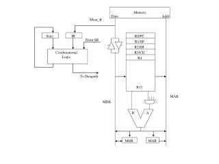
4 A D D M U X M U X ADD Shift Left 2 AND jmp 25-00 zero br PC 25-21 INST MEMORY RA1 REG FILE RD1 IA 20-16 RA2 DATA MEMORY 31-00 INST ALU MA M U X RD2 M U X WA WD 15-11 WE WD MD M U X MR MW RDES Sign Ext ALU CON ALUSRC 15-00 05-00 ALUOP Memreg CONTROL 31-26 Data Path Operation
Our Simple Control Structure • All of the logic is combinational • We wait for everything to settle down, and the right thing to be done • ALU might not produce “right answer” right away • we use write signals along with clock to determine when to write • Cycle time determined by length of the longest path We are ignoring some details like setup and hold times
4 A D D M U X M U X ADD Shift Left 2 AND jmp 25-00 zero br PC 25-21 INST MEMORY RA1 REG FILE RD1 IA 20-16 RA2 DATA MEMORY 31-00 INST ALU MA M U X RD2 M U X WA WD 15-11 WE WD MD M U X MR MW RDES Sign Ext ALU CON ALUSRC 15-00 05-00 ALUOP Memreg CONTROL 31-26 Control Points
4 A D D M U X M U X ADD Shift Left 2 AND jmp 25-00 zero br PC 25-21 INST MEMORY RA1 REG FILE RD1 IA 20-16 RA2 DATA MEMORY 31-00 INST ALU MA M U X RD2 M U X WA WD 15-11 WE WD MD M U X MR MW RDES Sign Ext ALU CON ALUSRC 15-00 05-00 ALUOP Memreg CONTROL 31-26 LW Instruction Operation
4 A D D M U X M U X ADD Shift Left 2 AND jmp 25-00 zero br PC 25-21 INST MEMORY RA1 REG FILE RD1 IA 20-16 RA2 DATA MEMORY 31-00 INST ALU MA M U X RD2 M U X WA WD 15-11 WE WD MD M U X MR MW RDES Sign Ext ALU CON ALUSRC 15-00 05-00 ALUOP Memreg CONTROL 31-26 SW Instruction Operation
4 A D D M U X M U X ADD Shift Left 2 AND jmp 25-00 zero br PC 25-21 INST MEMORY RA1 REG FILE RD1 IA 20-16 RA2 DATA MEMORY 31-00 INST ALU MA M U X RD2 M U X WA WD 15-11 WE WD MD M U X MR MW RDES Sign Ext ALU CON ALUSRC 15-00 05-00 ALUOP Memreg CONTROL 31-26 R-Type Instruction Operation
4 A D D M U X M U X ADD Shift Left 2 AND jmp 25-00 zero br PC 25-21 INST MEMORY RA1 REG FILE RD1 IA 20-16 RA2 DATA MEMORY 31-00 INST ALU MA M U X RD2 M U X WA WD 15-11 WE WD MD M U X MR MW RDES Sign Ext ALU CON ALUSRC 15-00 05-00 ALUOP Memreg CONTROL 31-26 BR-Instruction Operation
4 A D D M U X M U X ADD Shift Left 2 AND jmp 25-00 zero br PC 25-21 INST MEMORY RA1 REG FILE RD1 IA 20-16 RA2 DATA MEMORY 31-00 INST ALU MA M U X RD2 M U X WA WD 15-11 WE WD MD M U X MR MW RDES Sign Ext ALU CON ALUSRC 15-00 05-00 ALUOP Memreg CONTROL 31-26 Jump Instruction Operation
Control • For each instruction • Select the registers to be read (always read two) • Select the 2nd ALU input • Select the operation to be performed by ALU • Select if data memory is to be read or written • Select what is written and where in the register file • Select what goes in PC • Information comes from the 32 bits of the instruction • Example: add $8, $17, $18 Instruction Format: 000000 10001 10010 01000 00000 100000 • op rs rt rd shamt funct
ALU Control • ALU's operation based on instruction type and function code • e.g., what should the ALU do with any instruction • Example: lw $1, 100($2) • 35 2 1 100 • op rs rt 16 bit offset • ALU control input000 AND 001 OR 010 add 110 subtract 111 set-on-less-than • Why is the code for subtract 110 and not 011?
ALUOp computed from instruction type Other Control Information • Must describe hardware to compute 3-bit ALU conrol input • given instruction type 00 = lw, sw 01 = beq, 10 = arithmetic • 11 = Jump • function code for arithmetic • Control can be described using a truth table:
Implementation of Control • Simple combinational logic to realize the truth tables
Timing: Single Cycle Implementation • Calculate cycle time assuming negligible delays except: • memory (2ns), ALU and adders (2ns), register file access (1ns)
Where we are headed • Design a data path for our machine specified in the next 3 slides • Single Cycle Problems: • what if we had a more complicated instruction like floating point? • wasteful of area • One Solution: • use a “smaller” cycle time and use different numbers of cycles for each instruction using a “multicycle” datapath:
Machine Specification • 16-bit data path (can be 4, 8, 12, 16, 24, 32) • 16-bit instruction (can be any number of them) • 16-bit PC (can be 16, 24, 32 bits) • 16 registers (can be 1, 4, 8, 16, 32) • With m register, log m bits for each register • Offset depends on expected offset from registers • Branch offset depends on expected jump address • Many compromise are made based on number of bits in instruction
Instruction • LW R2, #v(R1) ; Load memory from address (R1) + v • SW R2, #v(R1) ; Store memory to address (R1) + v • R-Type – OPER R3, R2, R1 ; Perform R3 R2 OP R1 • Five operations ADD, AND, OR, SLT, SUB • I-Type – OPER R2, R1, V ; Perform R2 R1 OP V • Four operation ADDI, ANDI, ORI, SLTI • B-Type – BC R2, R1, V; Branch if condition met to address PC+V • Two operation BNE, BEQ • Shift class – SHIFT TYPE R2, R1 ; Shift R1 of type and result to R2 • One operation • Jump Class -- JAL and JR (JAL can be used for Jump) • What are th implications of J vs JAL • Two instructions
Instruction bits needed • LW/SW/BC – Requires opcode, R2, R1, and V values • R-Type – Requires opcode, R3, R2, and R1 values • I-Type – Requires opcode, R2, R1, and V values • Shift class – Requires opcode, R2, R1, and shift type value • JAL requires opcode and jump address • JR requires opcode and register address • Opcode – can be fixed number or variable number of bits • Register address – 4 bits if 16 registers • How many bits in V? • How many bits in shift type? • 4 for 16 types, assume one bit shift at a time • How many bits in jump address?
Performance • Measure, Report, and Summarize • Make intelligent choices • See through the marketing hype • Key to understanding underlying organizational motivationWhy is some hardware better than others for different programs?What factors of system performance are hardware related? (e.g., Do we need a new machine, or a new operating system?)How does the machine's instruction set affect performance?
Which of these airplanes has the best performance? • How much faster is the Concorde compared to the 747? • How much bigger is the 747 than the Douglas DC-8? Airplane Passengers Range (mi) Speed (mph) Boeing 737-100 101 630 598 Boeing 747 470 4150 610 BAC/Sud Concorde 132 4000 1350 Douglas DC-8-50 146 8720 544
Computer Performance: TIME, TIME, TIME • Response Time (latency) — How long does it take for my job to run? — How long does it take to execute a job? — How long must I wait for the database query? • Throughput — How many jobs can the machine run at once? — What is the average execution rate? — How much work is getting done? • If we upgrade a machine with a new processor what do we increase? If we add a new machine to the lab what do we increase?
Execution Time • Elapsed Time • counts everything (disk and memory accesses, I/O , etc.) • a useful number, but often not good for comparison purposes • CPU time • doesn't count I/O or time spent running other programs • can be broken up into system time, and user time • Our focus: user CPU time • time spent executing the lines of code that are "in" our program
time Clock Cycles • Instead of reporting execution time in seconds, we often use cycles • Clock “ticks” indicate when to start activities (one abstraction): • cycle time = time between ticks = seconds per cycle • clock rate (frequency) = cycles per second (1 Hz. = 1 cycle/sec)A 200 Mhz. clock has a cycle time
How to Improve Performance So, to improve performance (everything else being equal) you can either________ the # of required cycles for a program, or________ the clock cycle time or, said another way, ________ the clock rate.
1st instruction 2nd instruction 3rd instruction ... 4th 5th 6th How many cycles are required for a program? • Could assume that # of cycles = # of instructions time This assumption is incorrect, different instructions take different amounts of time on different machines.Why?hint: remember that these are machine instructions, not lines of C code
Different numbers of cycles for different instructions • Multiplication takes more time than addition • Floating point operations take longer than integer ones • Accessing memory takes more time than accessing registers • Important point: changing the cycle time often changes the number of cycles required for various instructions (more later) time
Now that we understand cycles • A given program will require • some number of instructions (machine instructions) • some number of cycles • some number of seconds • We have a vocabulary that relates these quantities: • cycle time (seconds per cycle) • clock rate (cycles per second) • CPI (cycles per instruction) a floating point intensive application might have a higher CPI • MIPS (millions of instructions per second)this would be higher for a program using simple instructions
Performance • Performance is determined by execution time • Do any of the other variables equal performance? • # of cycles to execute program? • # of instructions in program? • # of cycles per second? • average # of cycles per instruction? • average # of instructions per second? • Common pitfall: thinking one of the variables is indicative of performance when it really isn’t.
# of Instructions Example • A compiler designer is trying to decide between two code sequences for a particular machine. Based on the hardware implementation, there are three different classes of instructions: Class A, Class B, and Class C, and they require one, two, and three cycles (respectively). The first code sequence has 5 instructions: 2 of A, 1 of B, and 2 of CThe second sequence has 6 instructions: 4 of A, 1 of B, and 1 of C.Which sequence will be faster? How much?What is the CPI for each sequence?
MIPS example • Two different compilers are being tested for a 100 MHz. machine with three different classes of instructions: Class A, Class B, and Class C, which require one, two, and three cycles (respectively). Both compilers are used to produce code for a large piece of software.The first compiler's code uses 5 million Class A instructions, 1 million Class B instructions, and 1 million Class C instructions.The second compiler's code uses 10 million Class A instructions, 1 million Class B instructions, and 1 million Class C instructions. • Which sequence will be faster according to MIPS? • Which sequence will be faster according to execution time?