Servo Control Using Analog Signal
This tutorial explores how to control a servo motor using an analog signal and Pulse Width Modulation (PWM) on a chipKIT board. Learn to obtain analog input values using the analogRead() function, which returns a value between 0 and 1023 (representing 0V to 3.3V). We will control the duty cycle of PWM using analogWrite(pin, value), with the output value ranging from 0 to 255. Demonstrations include fading an LED, creating a potentiometer-controlled LED, and adjusting LED brightness using increment and decrement. Follow the provided example sketches to see practical applications.

Servo Control Using Analog Signal
E N D
Presentation Transcript
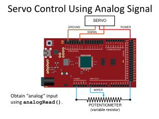
Servo Control Using Analog Signal Obtain “analog” input using analogRead().
Conversion of Analog to Digital • Obtain “analog” input using analogRead(). • analogRead()returns a value between 0 (if pin at ground) and 1023 (if pin at 3.3 V). • Argument of analogRead()is the pin to read(only pins labeled ANALOGIN can be used).
Pulse Width Modulation (PWM) 0% • On the chipKIT there are 490 periods per second. • Use analogWrite(pin, value) to controlthe duty cycle on a pin. • The value must be between 0 and 255. • The pin must be one of the underlined pins.
Pulse Width Modulation (PWM) • If you take the average value over one period,you can think of the voltage as being between0 V (0% duty cycle) and 3.3 V (100% duty cycle). • There are 256 different voltage levels. • Can demonstrate this with an LED attached topin 9 and the example sketch Fading.
Pulse Width Modulation (PWM) Upload example sketch Fading for this circuit.
Pulse Width Modulation (PWM) Write sketch led_with_potentiometer for this circuit.
Pulse Width Modulation (PWM) Write sketch led_with_inc_and_dec for this circuit.