Excavation & Trenching
Excavation & Trenching.

Excavation & Trenching
E N D
Presentation Transcript
Excavation & Trenching These handouts and documents with attachments are not final, complete, or definitive instruments. This information is for guidance purposes only. You should independently verify and satisfy yourself as to its accuracy. The AHBSIF does not assume any liability for damages arising from the use of this information or exhibits and attachments thereto and renders no opinion that any of the terms, conditions, and/or cited federal standards in this document and the exhibits and attachments should be explicitly followed by the fund member. Seek specific guidance from the appropriate regulator (OSHA) or professional advisor.
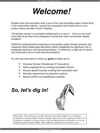
Dirt Work is Serious Business • Excavation cave-ins are one of the major sources of fatalities within the construction industry. • Trenching accidents on construction sites account for an estimated 100 fatalities/year. • 79% of trench fatalities occur in less than 15’ excavations: 38% in less than 10’. • Statistically most likely to be killed in an excavation: • Male • Construction Labor • 20 to 30 years old
News Releases • Michigan 09/29/10 • A construction worker killed Wednesday in a trench collapse west of Kalamazoo has been identified by police as Samuel Wilson, 58, of Burlington. Wilson was installing sewer piping in a trench that was 8 feet deep and 3 feet wide when the trench collapsed at 4:12 p.m., according to the Kalamazoo County Sheriff’s Office. At the time of the incident, Wilson, was working at the site of a house under construction in the 3200 block. Wilson was pronounced dead at the scene, deputies said.Undersheriff Pali Matyas said police planned to turn their investigation over today to the Michigan Occupational Safety and Health Administration. • Nebraska 06/05/10 • A Lewis and Clark Rural Water District employee died Friday after a trench collapsed around him in northern Knox County. The incident killed 48-year-old Galen Jueden of Hartington, Knox County Sheriff Jim Janecek said in a news release. Jueden and another worker were replacing water lines in the trench, about 5 or 6 feet deep, when it collapsed around Jueden at about 11 a.m. Friday, Sheriff's Capt. Ernest Ibach said. "He was only really buried about up to his waist," Ibach said. Telephone workers in the area pulled him from the trench and performed CPR, but neither they nor rescue workers could revive him. Jueden was pronounced dead at the scene.
OSHA’s Injury Data • The following hazards are most responsible for excavation related injuries; • No protective systems • Failure to inspect the trench before and during work • Improper spoils pile location • Access/egress issues
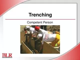
Defining a Competent Person • One who is capable of identifying existing and predictable hazards in the surroundings, or working conditions which are unsanitary, hazardous, or dangerous to employees, and who has authorization to eliminate them. • Competency for Subpart P requires knowledge of the following: • Soils analysis • The use of protective systems • The requirements of this standard A cubic yard of soil weighs approx. 2700 lbs!
Competent Person Responsibilities • Authority to stop work • Inspection of excavations • Daily • Pre-shift • As needed • After rain • Any increasing hazard occurrence • Testing for hazardous atmospheres • Inspection of material and equipment • Monitoring of water removal • Visual Tests • Manual Tests
Mechanics of a Cave-In • Stress cracks form back from edge due to ground surface tension and shear forces. • Cracks occur from about 1/3 to 2/3 of the depth of the excavation back from its edges. • Cracks take away the soils ability to maintain a strong vertical face. • The weight of the earth above is transferred to the lower portions of the excavation wall.
Mechanics of a Cave-In • Excavation bottoms are the first to fail. • Support for the upper part of excavation is left hanging only by shear and reduced tension forces. • The uppermost portion of the vertical wall collapses into the excavation. • Soil, like concrete, is normally strong in compression but not strong in tension. • Figures 1 and 2 two detail the scenario.
Mechanics of a Cave-In Fig. 1 Fig. 2
Soil Classification Cohesive Granular Stronger + - Weaker More Cohesion – Less Cohesion Clay Silt Sand
Soil Classification – Visual Tests • Observe samples of soil that are excavated. • If it stays in clumps it is cohesive • If it breaks up easily its granular • Check the sides of the opened excavation and adjacent surfaces for signs of cracking. • Check for existing utilities, underground structures, and previously disturbed soil. • Check for layered soils. • Be aware of surface water, seeping water, and water collection in the base. • Be aware of the machinery running near the cut. Vibration can affect stability.
Plasticity – Dry Strength • Plasticity – Mold a moist or wet sample of soil into a wet ball and attempt to roll it into threads as thin as 1/8-inch in diameter. Cohesive material can be successfully rolled into threads without crumbling. If at least a two-inch length of 1/8-inch thread can be held on one end without tearing, the soil is cohesive. • Dry Strength – If the soil is dry and crumbles on its own or with moderate pressure into individual grains or fine powder it is granular. If its dry and breaks into clumps, but the clumps can only be broken with difficulty, it may be a clay combination.
This test can be used to estimate the unconfirmed compressive strength of cohesive soils. Thumb Penetration Test • Type A: These soils can be indented by the thumb, but penetration takes great effort. • Type B: Easily indented, can be penetrated with somewhat less effort than type A. • Type C: This type of soil can be easily penetrated up to several inches by the thumb and can be molded with light finger pressure. Thumb Penetration
Pocket Penetrometer • Probes the soil with a small tube-like plunger • Device is pressed into soil to calibration mark • Spring loaded piston displaces the scale ring • Produces a compressive strength reading rated in tons/sq.ft
Shear Vane • Hand-held instrument used for determining soil strength • Provides reading in kPa (kiloPascal, Unit of Pressure) • Vane blade is pushed into the soil and device is rotated at predetermined rate (ex: 1 revolution/minute) • Reading is obtained when soil fails • Devices come with different ranges and features • Extension rods are available to increase the measurement depth
Sloping • When combination soils are encountered, and the soil beneath is of lesser cohesion than the soil above, the slope will be that of the less cohesive soil. • When sloping with a shoring system in place, the top edge of the cut must be 18” below the top edge of the shoring system. • A shoring device does not affect the soil type dimensions of the continuing slope.
Short Term Maximum Allowable Slopes • A short term maximum allowable slope is a special situation for Type A soil. • An excavation in Type A soil that is open for less than 24 hours and 12 feet or less in depth, can have a maximum allowable slope of 1/2H:1V (63°).
Benching • Can stand alone or in combination with sloping • Type C soils cannot be benched • In multiple bench situations, max bench height of first bench is 4’ • In bench-slope combinations, max bench height of first bench is 3.5’
Foundation/Basement Excavations • The depth of the foundation/basement trench cannot exceed 7½ feet deep unless you provide other cave-in protection. • Keep the horizontal width of the foundation trench at least 2 feet wide. Mind surface encumbrances. • Plan the foundation trench work to minimize workers in the trench and the length of time they spend there. • Inspect the trench regularly. • Stop work if any potential for cave-in develops and fix the problem before work starts again.
Utilities Location • Alabama One Call 1-800-292-8525 or 811 • Must call at least 48 hours in advance • Service is available Monday through Friday, 7:00 am to 5:00 pm • All utilities are marked in a standardized color code
Excavators must observe a tolerance zone The width of the facility on a horizontal plane, at least 18” on either side of the outside edge If relocation is necessary, excavator must coordinate with facility owner/operator Utilities Location
Utilities Location • When estimated location of underground installations are approached, exact location shall be determined by safe/acceptable means (hand digging, soft dig, pot hole, etc.) • While excavation is open, underground installations shall be protected, supported or removed as necessary to safeguard employees.
Uniform Color Codes See Appendix “C” • Electric – Red • Gas/Oil – Yellow • Comm./CATV – Orange • Water – Blue • Sewer – Green • Proposed Exc. – White • Temp. Survey - Pink
Protective Systems Reasons for Needing a Protecive System • Existing utility lines, roadways, or structural foundations intruding on the maximum allowable slope. • No right-of-way permit for sloped excavation. • The vertical face excavation is beyond the safety slope. • The gravitational force will cause soil raveling, cave-ins, or slope stability failures from the vertical face.
Protective Systems Struts Timber Shoring • System uses reinforced wood sheets or planks in an upright or sheet configuration to reinforce the vertical cut • Walers support the system horizontally against the outer wall • Struts support the system horizontally from side to side Walers
Protective Systems Hydraulic Shoring • Uses alloy struts (aluminum, steel) to support system side to side • System does not require entry for installation or removal • Significantly lighter than timber systems • Provides even distribution of pressure along the trench line • Can utilize "preloading" to use the soil's natural cohesion to prevent movement • Adapts easily to various trench depths and widths.
Protective Systems Trench Boxes • The width of the trench should exceed the width of the box to facilitate ease of movement • Clearance prevents stresses on the trench box that could lead to failure during cave-in • Trench boxes may sit on 2’ of excavated soil
Protective Systems Pro Tec Slide Rail System • Traditional shoring concept with less excavation • Channeled posts are pressed into place by excavator • Panels are inserted into post channels • System utilizes the soils natural compressive strength • Fast installation and removal • System conforms to a wide variety of excavation types
Access/ Egress • A stairway, ladder, ramp, or other safe means of egress shall be located in trench excavations that are 4 feet or more in depth and require no more than 25 feet of lateral travel for employees. • Must be designed by a competent person. • Boards must be of uniform thickness and structurally sound, also must be equipped with cleats to prevent tripping on ramp applications.
Hazardous Atmospheres • All testing must be performed from outside the space • Hazard may be generated from existing conditions inside excavation • Methane • Natural Gas • Petroleum • Hazard may be generated from surroundings • Carbon Monoxide
Hazardous Atmospheres Exposures to harmful levels of atmospheric contaminants can be prevented by: • Testing for oxygen deficient air with a tester at no less than four feet in depth. (Concentrations should lie between 19.5% and 23.5%) • Flammable gas testing • Toxic atmosphere testing. • Testing as often as is necessary to ensure safe atmosphere at all times
Standard Specifics • All spoils piles and equipment must be kept at least 2’ back from the excavation’s edge. • Employees must not be exposed to falling loads at any time. • Employees must be provided with and wear warning vests when exposed to traffic • Excavations greater than 5’ in depth must be sloped, benched, or utilize a protective system. • Water accumulation must be controlled at all times
Standard Specifics • Surface encumbrances must be removed or supported i.e. trees, telephone poles, fire hydrants • If a ramp must be constructed, handrails and decking must meet established requirements. • Employee ramps must be designed by a competent person. • Physical protection must be provided at all remotely located excavations. • Structural ramps used to support equipment must be designed by a Registered Professional Engineer