Multi-Level Logic Synthesis Introduction
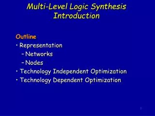
Multi-Level Logic Synthesis Introduction. Outline Representation Networks Nodes Technology Independent Optimization Technology Dependent Optimization. Structured System. (combinational logic, memory, I/O). Combinational optimization Sequential optimization.

Multi-Level Logic Synthesis Introduction
E N D
Presentation Transcript
Multi-Level Logic Synthesis Introduction Outline • Representation • Networks • Nodes • Technology Independent Optimization • Technology Dependent Optimization
Structured System (combinational logic, memory, I/O) • Combinational optimization • Sequential optimization
Two-Level (PLA) vs. Multi-Level PLA control logic constrained layout highly automatic technology independent multi-valued logic slower? input, output, state encoding Multi-level all logic general automatic partially technology independent coming soon!! can be high speed some results
Early Approaches to Multi-Level Algorithmic Approach • continues along lines of ESPRESSO and two-level minimization • spectrum of speed/quality trade-off algorithms • encourages development of understanding and theory
Optimization Cost Criteria The accepted optimization criteria for multi-level logic are to minimize some function of: • Area occupied by the logic gates and interconnect (approximated by literals = transistors in technology independent optimization) • Critical path delay of the longest path through the logic • Degree of testability of the circuit, measured in terms of the percentage of faults covered by a specified set of test vectors for an approximate fault model (e.g. single or multiple stuck-at faults) • Power consumed by the logic gates • Noise Immunity • Wireability while simultaneously satisfying upper or lower bound constraints placed on these physical quantities
Multi-Level is Natural for High Level Synthesis Example w=ab+ab’ Ifw, then z=cd+a’d’ ; u=cd+a’d’+e(f+b) else z=e(f+b) ; u=(cd+a’d’)e(f+b) A: w=ab+ab’ z=w(cd+a’d’ )+w’e(f+b) u=w(cd+a’d’+e(f+b))+w’((cd+a’d’)e(f+b)) B: w=ab+ab’ t=cd+a’d’ s=e(f+b) z=wt+w’s u=w(t+s)+w’ts
Network Representation In implementing multi-level logic our first aim is to establish a structure on which to develop a theory and algorithms • independent of technology on which manipulations can be made, and • optimization progresscan be well estimated. This leads to two abstractions: • Boolean network • Factored forms
Network Representation Boolean network: • directed acyclic graph (DAG) • node logic function representation fj(x,y) • node variableyj: yj= fj(x,y) • edge (i,j)if fjdepends explicitly on yi Inputs x = (x1, x2,…,xn ) Outputs z = (z1, z2,…,zp ) External don’t cares d1(x), d2(x) ,…, dp(x)
Network Representation Booleannetwork:
Node Representation Some choices: • Merged view (technology and network merged) • Separated view • technology dependent • technology independent • node representation general node generic node discrete node
Node Representation Separated, technology independent view,general node: • each node can be a representation of an arbitrary logic function • representation and implementation are the same • a theory is easier to develop since there are no arbitrary restrictions driven by technology • SIS uses this approach (includes all others as special cases, except for multiple output nodes) Choices of function representation for separated, technology independent view: • sum of products form • factored form • binary decision diagram
Sum of Products (SOP) Example: abc’+a’bd+b’d’+b’e’f (sum of cubes) Advantages: • easy to manipulate and minimize • many algorithms available (e.g. AND, OR, TAUTOLOGY) • two-level theory applies Disadvantages: • Not representative of logic complexity. For example f=ad+ae+bd+be+cd+ce f’=a’b’c’+d’e’ These differ in their implementation by an inverter, but their SOPs are not comparably complex. • hence not easy to estimate logic; difficult to estimate progress during logic manipulation
Reduced Ordered BDDs • like factored form, represents both function and complement • like network of muxes, but restricted since controlled by primary input variables • not really a good estimator for implementation complexity • given an ordering, reduced BDD is canonical, hence a good replacement for truth tables • for a good ordering, BDDs remain reasonably small for complicated functions (e.g. not multipliers) • manipulations are well defined and efficient • true support (dependency) is displayed
Factored Forms Example:(ad+b’c)(c+d’(e+ac’))+(d+e)fg Advantages • good representative of logic complexity f=ad+ae+bd+be+cd+ce f’=a’b’c’+d’e’ f=(a+b+c)(d+e) • in many designs (e.g. complex gate CMOS) the implementation of a function corresponds directly to its factored form • good estimator of logic implementation complexity • doesn’t blow up easily Disadvantages • not as many algorithms available for manipulation (research opportunity!) • hence usually just convert into SOP before manipulation
Factored Forms Note: literal count transistor count area (however, area also depends on wiring which is currently ignored)
Factored Forms Definition 1:f is an algebraic expression if f is a set of cubes (SOP), such that no single cube contains another (minimal with respect to single cube containment) Example:a+ab is not an algebraic expression (factoring gives a(1+b) ) Definition 2: the product of two expressions f and g is a set defined by fg = {cd | c f and d g and cd 0} Example:(a+b)(c+d+a’)=ac+ad+bc+bd+a’b Definition 3:fg is an algebraic product if f and g are algebraic expressions and have disjoint support (that is, they have no input variables in common) Example:(a+b)(c+d)=ac+ad+bc+bd is an algebraic product
Factored Forms Definition 4:A factored form can be defined recursively by the following rules. A factored form is either a product or sum where: • a product is either a single literal or product of factored forms • a sum is either a single literal or sum of factored forms A factored form is a parenthesized algebraic expression. Examples: a(b+c), abc+d’b, (a+b)(c+d), c, ab+c(d+b’) etc. In effect a factored form is a product of sums of products … or a sum of products of sums … Any logic function can be represented by a factored form, and any factored form is a representation of some logic function.
Factored Forma Examples of factored forms: x y’ abc’ a+b’c ((a’+b)cd+e)(a+b’)+e’ (a+b)’cis not a factored form since complementation is not allowed, except on literals. Three equivalent factored forms (factored forms are not unique): ab+c(a+b) bc+a(b+c) ac+b(a+c)
Factored Forms Definition 5:The factorization value of an algebraic factorization F=G1G2+R is defined to be fact_val(F,G2) = lits(F)-( lits(G1)+lits(G2)+lits(R) ) = (|G1|-1) lits(G2) + (|G2|-1) lits(G1) assuming G1, G2 and R are algebraic expressions. Where |H| is the number of cubes in the SOP form of H. Factorization value tells us how many literals are saved by expressing F in a factored way. Example: The algebraic expression F = ae+af+ag+bce+bcf+bcg+bde+bdf+bdg can be expressed in the form F = (a+b(c+d))(e+f+g), which requires 7 literals, rather than 24. If G1=(a+bc+bd) and G2=(e+f+g), then R=. fact_val(F,G2) = 23+25=16. The factored form above saves 17 literals, not 16. The extra literal comes from recursively applying the formula to the factored form of G1.
Factored Forms Factored forms are more compact representations of logic functions than the traditional sum of products form. For example, (a+b)(c+d(e+f(g+h+i+j)when represented as a SOP form is ac+ade+adfg+adfh+adfi+adfj+bc+bde+bdfg+ bdfh+bdfi+bdfj Of course, every SOP is a factored form but it may not be a good factorization.
Factored Forms When measured in terms of number of inputs, there are functions whose size is exponential in sum of products representation, but polynomial in factored form. Example: Achilles’ heel function There are n literals in the factored form and (n/2)2n/2 literals in the SOP form. Factored forms are useful in estimating area and delay in a multi-level synthesis and optimization system, because: in many design styles (e.g. complex gate CMOS design) the implementation of a function corresponds directly to its factored form.
Factored Forms Factored forms can be graphically represented as labeled trees, called factoring trees, in which each internal node including the root is labeled with either +or, and each leaf has a label of either a variable or its complement (i.e. a literal) Example:factoring tree of ((a’+b)cd+e)(a+b’)+e’
Factored Forms The size of a factored form F (denoted (F )) is the number of literals in the factored form. Example:(( a+b)ca’) = 4((a+b+cd)(a’+b’)) = 6 A factored form is optimal if no other factored form (for that function) has less literals. A factored form is positive unate in x,if x appears in F, but x’ does not. A factored form is negative unate in x,if x’ appears in F, but x does not. F is unate in x if it is either positive or negative unate in x, otherwise F is binate in x. Example: (a+b’)c+a’ is positive unate in c, negative unate in b, and binate in a.
Cofactor of Factored Forms The cofactor of a factored form F, with respect a literalx1 (or x1’ ), is the factored form Fx1= Fx1=1(x)(or Fx1’=Fx1=0(x) ) obtained by • replacing all occurrences of x1by 1, and x1’ by 0 • simplifying the factored form using the Boolean algebra identities 1y=y 1+y=1 0y=0 0+y=y • after constant propagation (all constants are removed), part of the factored form may appear as G + G. In general, G is another factored form, and the G’s may have different factored forms.
Cofactor of Factored Forms The cofactor of a factored form F, with respect to a cube c, is a factored form FC obtained by successively cofactoring F with each literal in c. Example:F = (x+y’+z)(x’u+z’y’(v+u’))andc = vz’. Then Fz’ = (x+y’)(x’u+y’(v+u’)) Fz’ v = (x+y’)(x’u+y’)
SOPs forms are used as the internal representation of logic functions in most multi-level logic optimization systems. Advantages good algorithms for manipulating them are available Disadvantages performance is unpredictable - they may accidentally generate a function whose SOP form is too large factoring algorithms have to be used constantly to provide an estimate for the size of the Boolean network, and the time spent on factoring may become significant Possible solution avoid SOP representation by using factored forms as the internal representation this is not practical unless we know how to perform logic operations directly on factored forms without converting to SOP forms extensions to factored forms of the most common logic operations have been partially provided, but more research is needed Factored Forms
Manipulation of Boolean Networks Basic Techniques: • structural operations (change topology) • algebraic • Boolean • node simplification (change node functions) • don’t cares • node minimization
Structural Operations Restructuring Problem: Given initial network, find best network. Example: f1 = abcd+abce+ab’cd’+ab’c’d’+a’c+cdf+abc’d’e’+ab’c’df’ f2 = bdg+b’dfg+b’d’g+bd’eg minimizing, f1 = bcd+bce+b’d’+a’c+cdf+abc’d’e’+ab’c’df’ f2 = bdg+dfg+b’d’g+d’eg factoring, f1 = c(b(d+e)+b’(d’+f)+a’)+ac’(bd’e’+b’df’) f2 = g(d(b+f)+d’(b’+e)) decompose, f1 = c(x+a’)+ac’x’ f2 = gx x = d(b+f)+d’(b’+e) Two problems: • find good common subfunctions • effect the division
Structural Operations Basic Operations: 1. Decomposition (single function) f = abc+abd+a’c’d’+b’c’d’ f = xy+x’y’ x = ab y = c+d 2. Extraction (multiple functions) f = (az+bz’)cd+e g = (az+bz’)e’ h = cde f = xy+e g = xe’ h = ye x = az+bz’ y = cd 3. Factoring (also called series-parallel decomposition) f = ac+ad+bc+bd+e f = (a+b)(c+d)+e
Structural Operations 4. Substitution (try to express one node in terms of another) g = a+b f = a+bc f = g(a+b) 5. Collapsing (also called elimination) f = ga+g’b g = c+d f = ac+ad+bc’d’ g = c+d Note:“division” plays a key role in all of these
Factoring vs. Decomposition Factoringf=(e+g’)(d(a+c)+a’b’c’)+b(a+c) Decomposition:y(b+dx)+xb’y’ Note: this is similar to BDD collapsing of common nodes and using negative pointers. But not canonical, so don’t have perfect identification of common nodes. tree DAG
Value of a Node and Elimination where ni = number of times literalsyj and yj’ occur in factored form fi lj = number of literals in factored fj with factoring without factoring value = (without factoring) - (with factoring) = # literals saved by factoring Can treat yj and yj’ the same since ( Fj ) = ( Fj’ ).
Value of a Node and Elimination Literals before = 5+7+5 = 17 Literals after = 9+15 = 24 --- 7 x Difference after - before = value = 7 But we may not have the same value if we were to eliminate, simplify and then re-factor.
Value of a Node and Elimination Note: value of a node can change during elimination