Logic Synthesis
Logic Synthesis. Introduction . Organization. Instructor: Adnan Aziz ACE 6.120 Email: adnan AT ece utexas edu Web: www.ece.utexas.edu/~adnan GPS: Longitude 30.287253, Latitude -97.736832 Office Hours: MW, 10:00am – 11:00am. Grading. Homework (~ 8 homeworks):

Logic Synthesis
E N D
Presentation Transcript
Logic Synthesis Introduction
Organization Instructor: Adnan Aziz ACE 6.120 Email: adnan AT ece utexas edu Web: www.ece.utexas.edu/~adnan GPS: Longitude 30.287253, Latitude -97.736832 Office Hours: MW, 10:00am – 11:00am
Grading • Homework (~ 8 homeworks): • purpose is to solidify material and make you think deeper about concepts • team work allowed, but each problem solution should be stated in your own words • Midterms • 1 after first half • 1 after 75% • Course project: • will start about halfway through course • final report (like conference paper) • Grader • TBD • Website: • http://www.ece.utexas/edu/~adnan/syn-07
Homework • About two-thirds written • theoretical problems • hand calculations • One third programming assignments: • to be written in C in SIS environment • assignment is typically: • write some application (e.g., build a particular circuit representation) • run some benchmarks on it • code and results (e.g. table of statistics) is to be turned in as .tar file in to grader
System Level Register Transfer Level Gate Level Transistor Level Layout Level Mask Level Design of Integrated Systems Verification Design
System Level • Abstract algorithmic description of high-level behavior • e.g. C-Programming language • abstract because it does not contain any implementation details for timing or data • efficient to get a compact execution model as first design draft • difficult to maintain throughout project because no link to implementation Port* compute_optimal_route_for_packet(Packet_t *packet, Channel_t *channel) { static Queue_t *packet_queue; packet_queue = add_packet(packet_queue, packet); ... }
RTL Level • Cycle accurate model “close” to the hardware implementation • bit-vector data types and operations as abstraction from bit-level implementation • sequential constructs (e.g. if - then - else, while loops) to support modeling of complex control flow module mark1; reg [31:0] m[0:8192]; reg [12:0] pc; reg [31:0] acc; reg[15:0] ir; always begin ir = m[pc]; if(ir[15:13] == 3b’000) pc = m[ir[12:0]]; else if (ir[15:13] == 3’b010) acc = -m[ir[12:0]]; ... end endmodule
4ns 3ns 5ns Gate Level • Model on finite-state machine level • models function in Boolean logic using registers and gates • various delay models for gates and wires • in this lecture we will mostly deal with gate level 1ns
Transistor Level • Model on CMOS transistor level • depending on application function modeled as resistive switches • used in functional equivalence checking • or full differential equations for circuit simulation • used in detailed timing analysis
Layout Level • Transistors and wires are laid out as polygons in different technology layers such as diffusion, poly-silicon, metal, etc.
Design of Integrated Systems - Design phases overlap to large degrees - Parallel changes on multiple levels, multiple teams - Tight scheduling constraints for product Logic Relative Effort Transistor RTL System Project Time
Design Challenges • Systems are becoming huge, design schedules are getting tighter • > 100 Mio gates becoming common for ASICs • > 0.4 Mio lines of C-code to describe system behavior • > 5 Mio lines of RLT code • Design teams are getting very large for big projects • several hundred people • differences in skills • concurrent work on multiple levels • management of design complexity and communication very difficult • Design tools are becoming more complex but still inadequate • typical designer has to run ~50 tools on each component • tools have lots of bugs, interfaces do not line up etc.
Design Challenges • Decision about design point very difficult • compromise between performance / costs / time-to-market • decision has to be made 2-3 years before design finished • design points are difficult to predict without actually doing the design • scheduling of product cycles • Functional verification • simulation still main vehicle for functional verification but inadequate because of size of design space • results in bugs in released hardware that is very expensive to recover from (different in software ;-)
Design Challenges • Fundamental tradeoffs between different modeling levels: • modeling detail and team size to maintain model • high-level models can be maintained by one or two people • detailed models need to be partitioned which results in a significant communication overhead • modeling accuracy versus modeling compactness • compact models omit details and give only crude estimations for implementation • detailed models are lengthy and difficult to adopt for major changes in design points • simulation speed versus hardware performance • high-level models can be simulated fast but cannot be implemented efficiently with automatic means • low-level models can be made to have a fast implementation but cannot be simulated very fast
General Design Approach • How do engineers build a bridge? • Divide and conquer !!!! • partition design problem into many sub-problems which are manageable • define mathematical model for sub-problem and find an algorithmic solution • beware of model limitations and check them !!!!!!! • implement algorithm in individual design tools, define and implement general interfaces between the tools • implement checking tools for boundary conditions • concatenate design tools to general design flows which can be managed • see what doesn’t work and start over
Design Automation • Design Automation is one of the most advanced areas in practical computer science • many problems require sophisticated mathematical modeling • many algorithms are computationally hard and require advanced and fine-tuned heuristics to work on realistic problem sizes • boundary conditions need to be well declared and synchronized between different tools (patchwork to cover all wholes) • Two common pitfalls in CAD research • problem is looking for a solution: • problem scope is too big, makes modeling difficult or algorithms don’t scale • problem scope is too small, solutions are not good enough • solution is looking for a problem: • model was oversimplified because real problem was too complex with too many boundary conditions
Key to Success • Fine-tuned combination of Design Methodology and Tools • addresses algorithmic complexity by requiring • manual partitioning of the problem • manual input of hints/suggestions • manual iterations to drive tool application to best solution • makes CAD systems and design flows very complex and difficult to manage Problem space Tools applicable Practical combination through design methodology
Examples of Divide and Conquer • RLT cycle simulation does only evaluate the next state logic of the circuits, timing is assumed to be correct • combination of static timing analysis, formal equivalence checking, and cycle simulation allows separation of issues • cycle simulation avoids expensive event scheduling and processing and performs significantly faster • However: • timing analysis is conservative with respect to the achievable clock cycle time
Examples of Divide and Conquer • Static timing analysis assumed simple gate delay models • complexity of static timing analysis becomes linear (simple longest and shortest paths analysis in circuit implementation) • very efficient implementation of incremental static timing analysis which is needed in the inner loop of the technology dependent part of logic synthesis • However: • actual gate delay varies a lot in reality • models often assume average fan-out rather than actual gate load • delay model assumes ideal signals • slew dependency ignored
Examples of Divide and Conquer • Logic synthesis assumes ideal gates which are independent of physical environment • standard cell place and route technology has made logic synthesis possible • gates are heavily over-designed to be functional in a wide variety of combinations (e.g. range of fan-out gates possible, different wire loads • layout placement and route done in standard rows that minimize latch-up effects and optimize power and clock wiring • However: • layout implementation remains sub-optimal because cells are designed for worst case application and with large safety margins with respect to environment
Examples of Divide and Conquer • Logic synthesis uses crude model to estimate circuit area • literal count or simple table-lookup for gates sizes allows fast comparison of different implementation choices • However: • actual gate size can vary to a very large degree depending on load and timing requirement • area for wiring completely ignored
Examples of Divide and Conquer • Formal equivalence checking assumes identical state encoding of the two designs to be compared • reduces the general equivalence checking problem to combinational equivalence checking which is computationally less complex • exploitation of structural similarities between designs to be compared makes tools applicable for huge (multi-million gate) designs • automatic algorithms for identifying register correspondence compensate to some extent for limited model • However: • combinational verification model cannot handle sequential verification problems
Full Custom Design Flow • Application: ultra-high performance designs • general-purpose processors, DSPs, graphic chips, internet routers, games processors etc. • Target: very large markets with high profit margins • e.g. PC business • Complexity: very complex and labor intense • involving large teams • high up-front investments and relatively high risks • Role of Logic Synthesis: • limited to components that are not performance critical or that might change late in design cycle (due to designs bugs found late) • control logic • non-critical data paths logic • bulk of data-path components and fast control logic are manually crafted for optimal performance
Full Custom Design Flow • Incomplete picture: ISA Specification Logic Synthesis Simulation RTL Spec Simulation Formal Equivalence Checking Gate Level Netlist Transistor Level Circuit Circuit Simulation Extract&Compare Layout Manual or semi-automatic Design Design Rule Checker
ASIC Design Flow • Application: general IC market • peripheral chips in PCs, toys, handheld devices etc. • Target: small to medium markets, tight design schedules • e.g. consumer electronics • Complexity of design: standard design style, quite predictable • standard flows, standard off-the-shelf tools • Role of Logic Synthesis: • used on large fraction of design except for special blocks such as RAM’s, ROM’s, analog components
ASIC Design Flow • Incomplete picture: Informal Specification Logic Synthesis RTL Spec Simulation Formal Equivalence Checking Gate Level Netlist Modifies Gate Level Netlist Static Timing Analysis Manual Changes to fix timing Test Logic Insertion ASIC Foundry
What is Logic Synthesis? Given: Finite-State Machine F(X,Y,Z, , ) where: X Y X: Input alphabet Y: Output alphabet Z: Set of internal states : X x Z Z (next state function) : X x Z Y (output function) D Target: Circuit C(G, W) where: G: set of circuit components g {Boolean gates, flip-flops, etc} W: set of wires connecting G
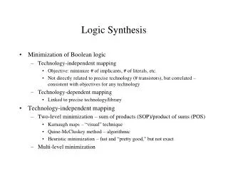
Objective Function for Synthesis • Minimize area • in terms of literal count, cell count, register count, etc. • Minimize power • in terms of switching activity in individual gates, deactivated circuit blocks, etc. • Maximize performance • in terms of maximal clock frequency of synchronous systems, throughput for asynchronous systems • Any combination of the above • combined with different weights • formulated as a constraint problem • “minimize area for a clock speed > 300MHz” • More global objectives • feedback from layout • actual physical sizes, delays, placement and routing
Constraints on Synthesis • Given implementation style: • two-level implementation (PLA, CAMs) • multi-level logic • FPGAs • Given performance requirements • minimal clock speed requirement • minimal latency, throughput • Given cell library • set of cells in standard cell library • fan-out constraints (maximum number of gates connected to another gate) • cell generators
Instability of Logic Synthesis Experiment to write out netlist in middle of synthesis run and read back in w/o change
Brief History of Logic Synthesis • 1960s: first work on automatic test pattern generation used for Boolean reasoning • D-Algorithm • 1978: Formal Equivalence checking introduced at IBM in production for designing mainframe computers • SAS tool based on the DBA algorithm • 1979: IBM introduced logic synthesis for gate array based main frame designed • LSS, next generation is BooleDozer • End 1986: Synopsys founded • first product “remapper” between standard cell libraries • later extended to full blown RTL synthesis • 1990s other synthesis companies enter the marker • Ambit, Compass, Synplicity. Magma, Monterey, ...
Why learning about Logic Synthesis? • Logic synthesis is the core of today's CAD flows for IC and system design • course covers many algorithms that are used in a broad range of CAD tools • basis for other optimization techniques, e.g. embedded software • basis for functional verification techniques • Most algorithms are computationally hard • covered algorithms and flows are good example for approaching hard algorithmic problems • course covers theory as well as implementation details • demonstrates an engineering approaches based on theoretical solid but also practical solutions • very few research areas can offer this combination
Course Outline • Representation of Boolean functions and basic algorithms • Boolean functions, formulas, circuits, cube representations, BDDs • efficient data structures and algorithms for manipulation and Boolean reasoning • SAT • Functional optimization of combinational circuits • two-level circuits • Quine McCluskey • Espresso • multi-level circuits • algebraic methods • structural transformation-based methods • technology mapping
Course Outline • Timing • timing models and timing analysis • timing optimization • Functional Optimization of Sequential Circuits • retiming • synchronous versus asynchronous circuits • state assignment and state minimization • reachability analysis • clock skew optimization • Low-power Synthesis • power analysis • low-power synthesis
Course Outline • Testing • testing problem and test models • automatic test pattern generation (ATPG) • Verification • formal equivalence checking • verification planning